Flash heating for tubing

a technology of flash heating and tubing, which is applied in the direction of steam generation using steam absorption, particle separator tubes, combustion air/fuel air treatment, etc., can solve the problems of equipment downtime, limit the maximum temperature that is acceptable for the sample tube, and the possibility of decomposition into unwanted substances, etc., to achieve the effect of improving the transport of electricity

Active Publication Date: 2009-09-17
LEIDOS SECURITY DETECTION & AUTOMATION INC
View PDF10 Cites 7 Cited by
  • Summary
  • Abstract
  • Description
  • Claims
  • Application Information

AI Technical Summary

Benefits of technology

[0015]According further to the system described herein, the clamp mechanism may embed the foil between two swaging rings, between a cylindrical ring and a snap ring, and/or between a cylindrical ring and a circular spring. The clamp mechanism may further optionally include at least one of a deformable electrically conductive metal o-ring, a deformable electrically conductive met

Problems solved by technology

Subsequent slow re-evaporation of the temporarily condensed sample gas leads to equipment downtime until all previous chemical substance has been purged from the chemical detector system.
Decomposition may also undesirably selectively remove a target gas species from the sample gas, and this limits the maximum temperature that is acceptable for the sample tube when sample gas is flowing through it.
If too hot a sampling tube is employed, decomposition into u

Method used


Image

  • Flash heating for tubing
  • Flash heating for tubing
  • Flash heating for tubing

Examples


embodiment 400

[0052]FIG. 5 is a schematic diagram of an embodiment 400 of the system described herein in which a cylindrical foil tube 410 is joined at an angle to another cylindrical foil tube 420 in order to make a tee joint. The tee-shaped junction of the two tubes may be at any desirable angle, including, for example, a right angle. A clamping mechanism at the end of the cylindrical foil tube 410 may include a shaped cylindrical ring 411 and a circular spring and / or a snap ring 412. The cylindrical foil tube 410 and its clamping mechanism may be inside and squeezed against the inside surface of the other cylindrical foil tube 420. An external clamp ring 413 may be employed to maintain the squeeze force and create a gas tight seal at the joint using a combination of screw and spring 414. The external clamp ring 413 may also provide an attachment point to complete the circuit for passing electricity through the cylindrical foil tube 410 and / or other cylindrical foil tube 420.

embodiment 500

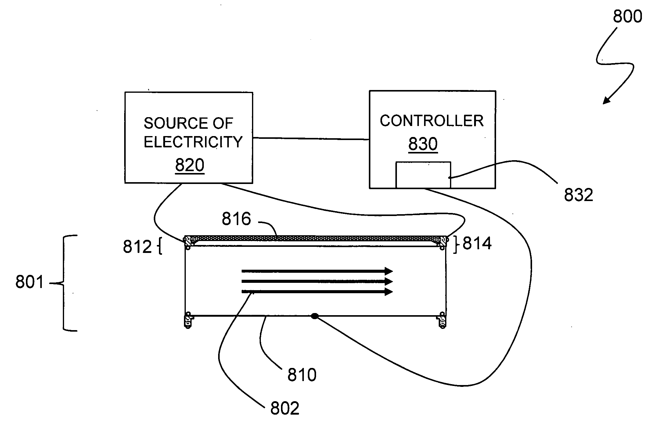
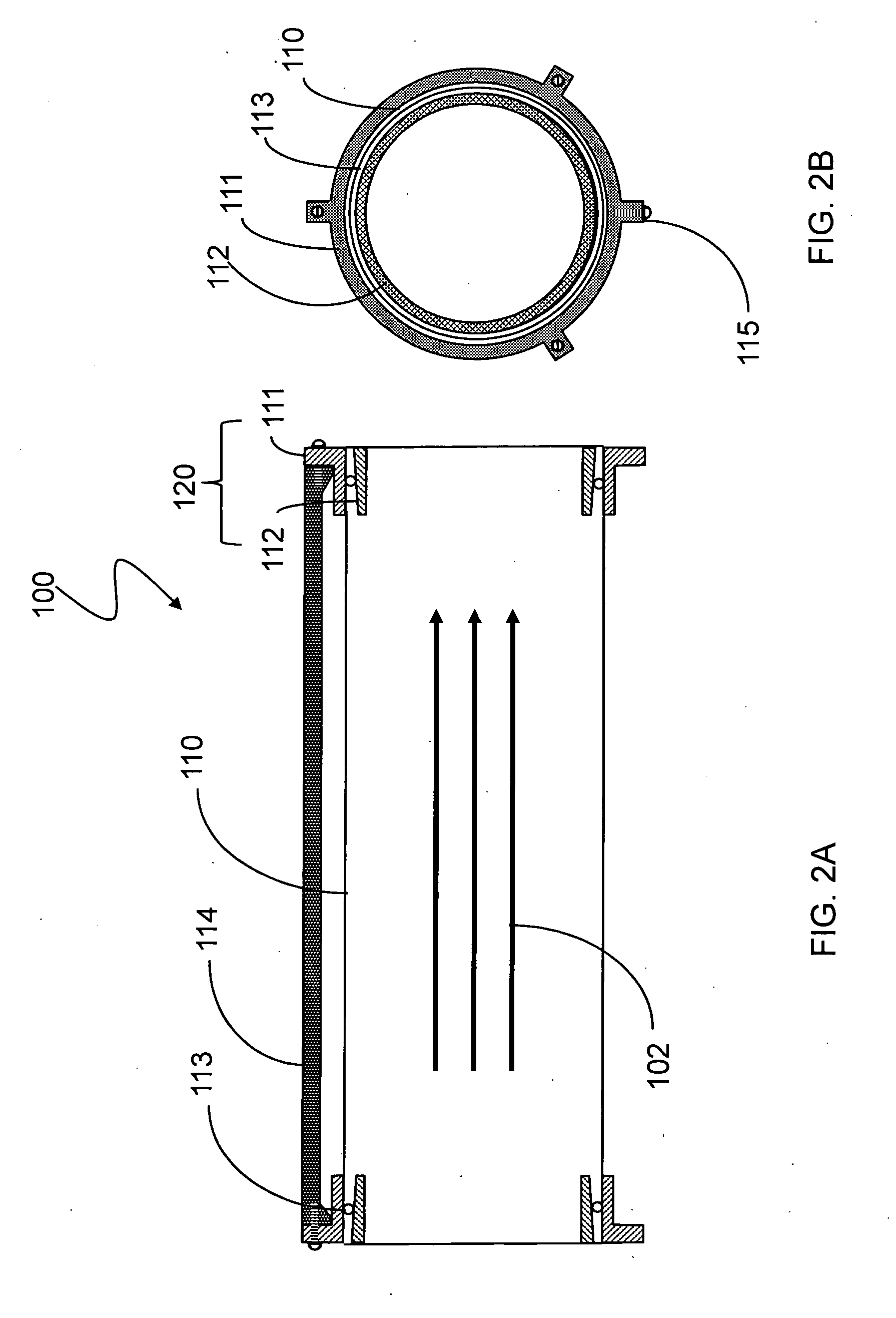
[0053]FIGS. 6A and 6B are schematic diagrams of an embodiment 500 of the system described herein in which a thin foil blank-off 516 is added to the end of the thin foil cylinder 510. FIG. 6A is a side cross-sectional view and FIG. 6B is an end view. If combined with the thin foil tee-connection illustrated in FIG. 5, an angled thin foil joint may also be provided. The thin foil 510 may be formed into a cylinder using a clamping mechanism provided by a cylindrical ring 511 and a circular spring and / or snap ring 512. One or more stiffeners 514 may be used to impart structural stability. A square or rectangular shaped electrically insulating end plate 515 may be squeezed against the cylindrical ring 511. The electrically insulating end plate 515 prevents electrical current that is passing through the thin foil blank-off 516 from interfering and shorting out electrical current that is passing through the thin foil 510. A clamping ring 517 may squeeze and seal the thin foil blank-off 516...


PUM

PropertyMeasurementUnit
Melting pointaaaaaaaaaa
Cooling rateaaaaaaaaaa

Abstract

A chemical sample gas tube that is capable of being rapidly heated and cooled allows rapid purging of condensed chemical vapor from its inside surface. The tube may include a thin foil with an electrically conducting surface, a rigidly separated pair of clamps to shape the thin foil into a cylinder shape, and a temperature-controlled source of electricity that can flow sequentially through the clamps and thin foil for heating. The temperature of the cylindrical thin foil may be increased at a rate of at least 25 degrees Celsius per second, and may be cooled at a rate of at least 10 degrees Celsius per second. A temperature control sequence may be provided that includes at least one temperature that performs at least one of: condensing the chemical vapor, transmitting the chemical vapor, desorbing the condensed chemical vapor, and decomposing the condensed chemical vapor.

Description

BACKGROUND OF THE INVENTION[0001]1. Field of the Invention[0002]This application relates to the field of detection of chemical substances and, more particularly, to improving the transport of vapors of chemical substances through tubing.[0003]2. Description of Related Art[0004]Chemical detection may be performed by a variety of detection instruments, such as a gas chromatograph, an ion mobility spectrometer, a mass spectrometer, and / or a differential mobility spectrometer. Many of these chemical detectors require that a chemical sample be vaporized and transported through a length of tubing (the “sample tube”) to reach the detection component. In order to avoid condensation of chemical species contained within the vapor sample (the “sample gas”), the walls of the sample tube may be heated.[0005]In some cases, the process of taking a sample begins with an operator rubbing an absorbent substance (the “sample trap”), such as chemical filter paper, onto the surface to be tested. Particl...

Claims


Application Information

Patent Timeline
IPC IPC(8): H05B3/00
CPCG01N1/2214B01L7/52
Inventor RICHARDS, KEITH A.BUNKER, STEPHEN N.
Owner LEIDOS SECURITY DETECTION & AUTOMATION INC
Why Eureka
Try Eureka