Aerodynamic fan control effector

Active Publication Date: 2009-09-17
THE BOEING CO
View PDF6 Cites 19 Cited by
  • Summary
  • Abstract
  • Description
  • Claims
  • Application Information

AI Technical Summary

Benefits of technology

[0014]The fan control effector may be employed to generate yawing moment about the aircraft as a substitute for other yaw control devices such as spoilers which are conventionally employed on aircraft. In this regard, the fan control effector provides aerodynamic yawing for an aircraft to augment and/or replace that which is conventionally obtained through conventional tail surfaces such as tail fins and/or rudders. In addition, the fan control effector advantageously provides aerodynamic yaw control at high angles of attack where a conventional vertical tail rudder may be ineffective. The fan control effector provides a solution for yaw control on tailless aircraft over that which is obtained with varying degrees of success with propulsive thrust control, split ailerons (i.e., spliterons) and spoilers.
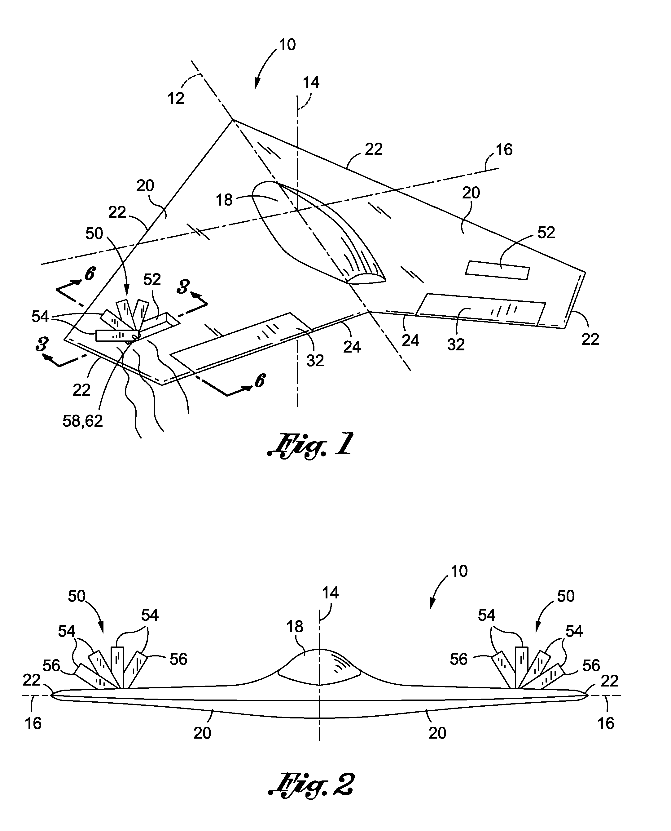
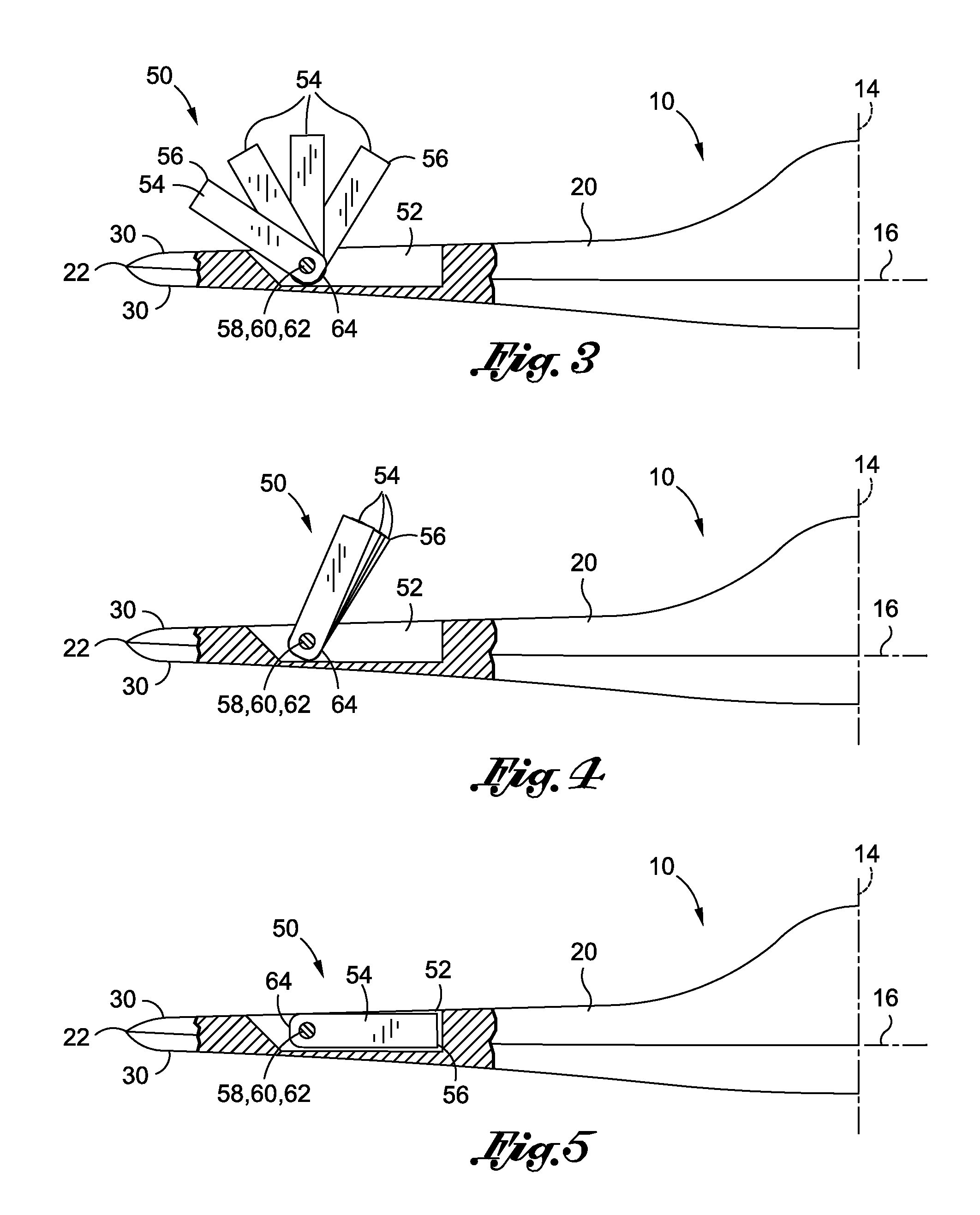
[0015]The fan control effector comprises at least one and, more preferably, a plurality of blades which are configured to be pivotably or rotatably deployed from the aircraft wing. Although illustrated in the figures as being generally elongate and/or rectangular shaped, the blades may be provided in any shape, size and configuration. It should also be noted that the fan control effector may comprise a single blade provided in any shape or size and which is configured to be deployable radially outwardly from a retracted position to a deployed position such that the blade extends out of the aircraft. In this regard, the blades extend preferably out of the upper-most surface of the wing and into the oncoming main flow passing over the wing.
[0016]In one embodiment, each of the blades may be configured to pivot about a pivot axis. The pivot axis may be oriented such that the blades rotate along an angular direction that is non-parallel with the main flow stream passing over the wing. For example, the pivot axis may be oriented such that the blades rotate through a plane that is substantially perpendicular relative to the longitudinal axis of the aircraft. However, the pivot axis may be oriented such that the plane of rotation of the blades is oriented in any direction including a direction that is parallel to the lon

Problems solved by technology

As is suggested by the name, tailless aircraft lack certain control surface arrangements typical of conventional aircraft such as aft-fuselage mounted tail sections for carrying a conventional elevator and/or stabilizer or a conventional tail fin and rudder.
Although the employment of spoilers and other devices has been effective in providing yaw control on tailless aircraft, the use of such devices presents certain drawbacks and deficiencies which detract from their overall utility for yaw control.
As such, the actuating mechanisms for spoilers and spliterons themselves must be capable of applying the relatively large deployment forces and are therefore typically large, bulky, complex, and heavy.
In addition, such actuating mechanisms may consume large amounts of energy for deployment of the control surfaces at certain flight conditions.
A further drawback associated with spliterons is related to the relatively thin cross-sectional profile at the trailing edge of the wing where spliterons are typically located.
Because of the relatively thin profile, packaging of the actuating mechanism for the spliteron presents design challenges.
The use of spoilers presents other inherent drawbacks.
For example, for spoilers that are mounted at a mid-chord position on the wing, the deployed spoiler may generate a disruption or separation in the airflow passing over the wing.
In this regard, spoilers may produce significant interference with flaps, ailerons and other downstream control surfaces due to the creation of separated flow in their wake.
In addition, the separated flow produced by the spoiler diminishes the downstream control surface effectiveness and, furthermore, may result in an increase in buffet loads on the aircraft.
As a result, tailless a

Method used


Image

  • Aerodynamic fan control effector
  • Aerodynamic fan control effector
  • Aerodynamic fan control effector

Examples


Embodiment Construction

[0030]Referring now to the drawings 20 wherein the showings are for purposes of illustrating the various and preferred embodiments of the invention only and not for purposes of limiting the same, FIG. 1 is a perspective rear illustration of an aircraft 10 having an embodiment of a fan control effector 50 disposed on a pair of wings 20. The exemplary aircraft 10 upon which the fan control effector 50 is installed is shown as a tailless aircraft 10 having a pair of opposing wings 20. The tailless aircraft 10 may include a fuselage and / or body 18 which may be integrated with the wings 20. The aircraft 10 illustrated in FIG. 1 includes a longitudinal axis 12 extending along the forward and aft directions of the aircraft 10 with a vertical axis 14 and horizontal axis 16 being oriented orthogonally relative to the longitudinal axis 12 as shown.

[0031]The aircraft 10 is shown as having a swept-wing 20 configuration with a pair of control surfaces such as elevons (i.e., combination elevator ...


PUM


Abstract

A fan control effector for an aircraft comprises at least one blade configured to be pivotably deployable in a radially outward direction from a retracted position to a deployed position such that the blade extends out of the aircraft. The fan control effector may be mounted in a symmetrical arrangement about a longitudinal axis on opposing wings of the aircraft. Furthermore, the fan control effector may comprise any number of blades for independent deployment outwardly from the wing. The blades are configured to be angularly deployable along a direction that is non-parallel to the longitudinal axis of the aircraft. The blades may be configured to be deployable sequentially from the wing starting with an initial deployment of an aft-most one of the blades.

Description

CROSS-REFERENCE TO RELATED APPLICATIONS(Not Applicable)STATEMENT RE: FEDERALLY SPONSORED RESEARCH / DEVELOPMENT(Not Applicable)FIELD[0001]The present invention relates generally to aircraft control systems and, more particularly, to a fan control effector that is configured to be radially outwardly deployable such as from an aircraft wing in order to generate yaw moment about the aircraft.BACKGROUND[0002]Tailless aircraft provide certain advantages over conventional aircraft such as improved aerodynamic efficiency due to reduced aerodynamic drag as well as reduced weight and size. Other advantages of tailless aircraft include low radar visibility due, at least in part, to the geometric configuration of the aircraft. As is suggested by the name, tailless aircraft lack certain control surface arrangements typical of conventional aircraft such as aft-fuselage mounted tail sections for carrying a conventional elevator and / or stabilizer or a conventional tail fin and rudder.[0003]In the ab...

Claims


Application Information

Patent Timeline
IPC IPC(8): B64C9/00
CPCB64C9/32B64C9/323B64C9/34Y02T50/44Y02T50/12Y02T50/32B64C39/10Y02T50/10Y02T50/30Y02T50/40
Inventor OSBORNE, BRADLEY A.SCHWIMLEY, SCOTT L.
Owner THE BOEING CO
Why Eureka
Try Eureka