Wind turbine energy storage and frequency control

a technology of wind power and frequency control, applied in the field of energy storage, can solve the problem that the variable nature of wind power is becoming less acceptable to utility companies

Active Publication Date: 2009-09-17
GENERAL ELECTRIC CO
View PDF22 Cites 101 Cited by
  • Summary
  • Abstract
  • Description
  • Claims
  • Application Information

AI Technical Summary

Problems solved by technology

As new grid codes are developed for wind farms, and as market penetration level of wind farms increases, variability of wind power is becoming less acceptable to utility companies.

Method used


Image

  • Wind turbine energy storage and frequency control
  • Wind turbine energy storage and frequency control
  • Wind turbine energy storage and frequency control

Examples


Embodiment Construction

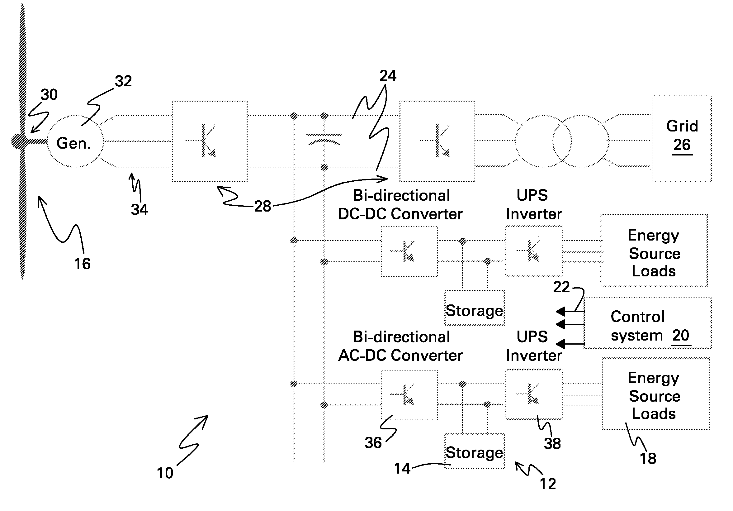
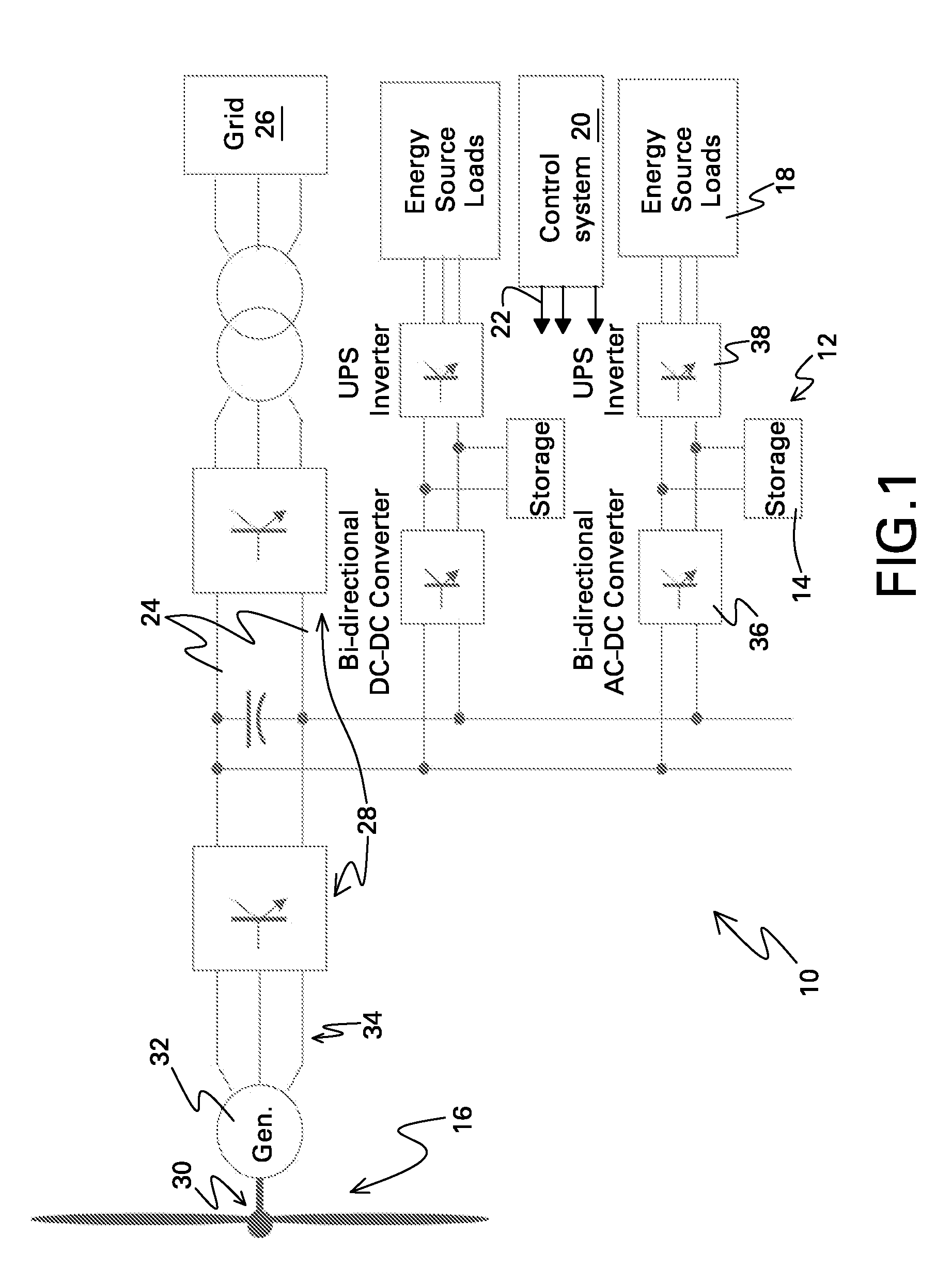
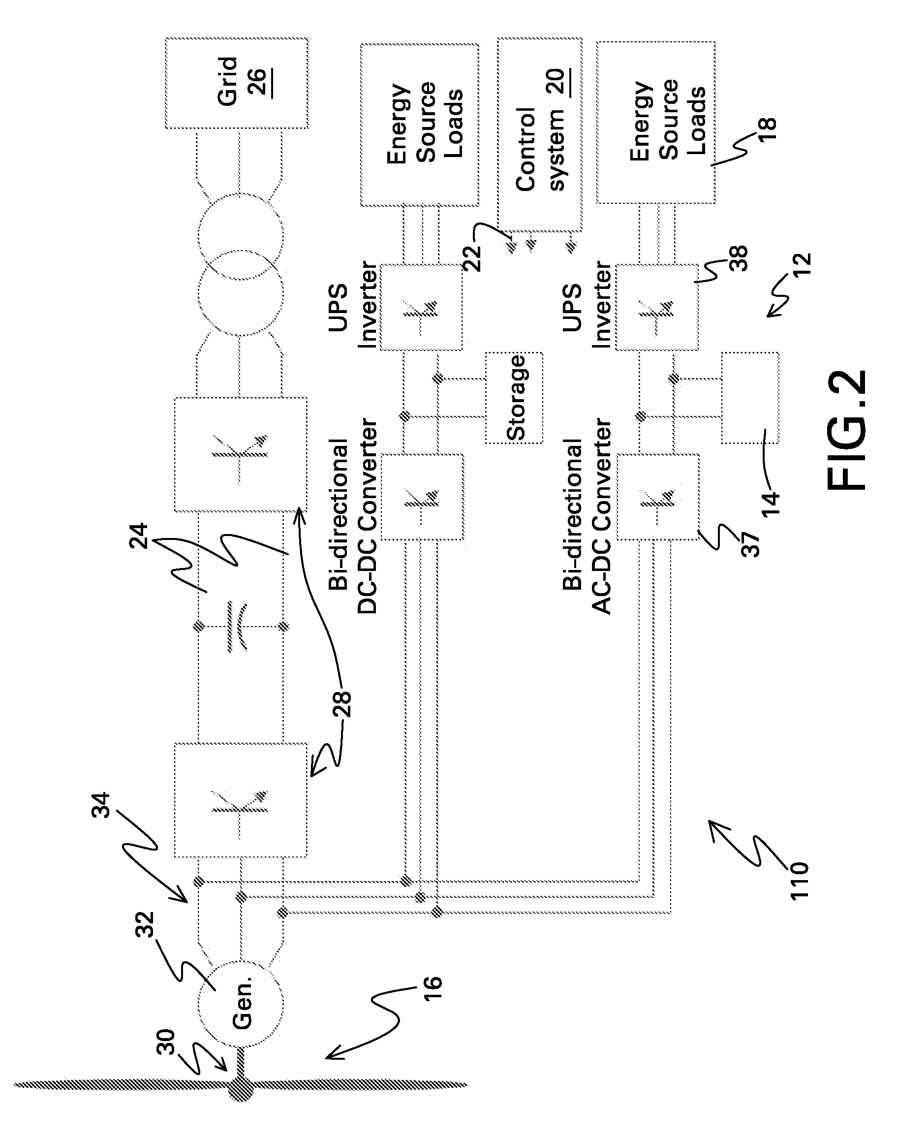
[0016]In embodiments described herein, dual-use energy storage is added to energy sources, particularly renewable energy sources such as wind turbines 30 (shown in FIG. 1), for enhanced performance and energy capture. Wind turbines typically already include uninterruptible power supply (UPS) equipment with energy storage for critical bus loads. Embodiments disclosed herein use storage to support the critical bus loads and other auxiliary loads as well as to provide power support for a power conversion system supplying power from the energy source to a network or grid. As used herein “a,”“an,” and other forms of the singular are meant to encompass one or more elements unless clearly indicated otherwise.

[0017]FIG. 1, for example, is a block diagram of an energy storage system 10 comprising: an uninterruptible power supply (UPS) system 12 comprising an energy storage device 14 coupled between an energy source 16 and an auxiliary load 18 of energy source 16; and a control system 20 conf...


PUM


Abstract

Commands are generated for controlling a state of charge of an energy storage device coupled between an energy source and an auxiliary load. Commands are also generated for providing from the energy storage device to the auxiliary load and for using power from the energy storage device for controlling a DC link voltage, energy source torque, grid side power flow, or combinations thereof. Commands may also be generated to provide frequency compatible power to auxiliary loads of the energy source.

Description

BACKGROUND[0001]The invention relates generally to energy storage and more specifically to the use of energy storage for multiple purposes of renewable energy sources. The invention additionally relates to wind turbines and more specifically to grid frequency flexibility in wind turbine electrical systems.[0002]Wind turbines have bladed rotors which are connected to electrical generators by shafts. Examples of electrical generators include doubly fed induction generators (DFIGs) and permanent magnet (PM) generators. In order to feed the electrical power to the grid, power electronics elements are used for power conditioning. In one example, the power electronics elements include back-to-back voltage source converters connected to a DC link. For a DFIG, stator terminals of the generator are directly connected to the grid, and the power electronics is connected between the rotor and stator terminals. For a PM machine, AC machine terminals are connected via the power electronics.[0003]...

Claims


Application Information

Patent Timeline
Patent Type & Authority Applications(United States)
IPC IPC(8): F03D9/02H02J7/14
CPCF03D9/003F03D9/021F05B2260/75F05B2270/10711F05B2270/337H02J3/386Y02B10/72Y02E10/763Y02E10/766Y02E10/72H02J9/062F03D9/11F03D9/255H02J2300/28H02J3/381Y02B10/70Y02E10/76Y02E70/30
Inventor BURRA, RAJNI KANTDELMERICO, ROBERT WILLIAMTEICHMANN, RALPHJAIN, ABHITAPSHU, MARK
Owner GENERAL ELECTRIC CO
Why Eureka
Try Eureka