Differential amplifier and drive circuit of display device using the same

a technology of differential amplifier and drive circuit, which is applied in the direction of differential amplifiers, amplifiers with semiconductor devices/discharge tubes, instruments, etc., can solve the problems of increased static power dissipation of each amplifier, deterioration of output deviation in the vicinity of power supply voltage, and shortage of discharging capability of positive-polarity output buffer amplifiers. achieve the effect of low power dissipation and high speed operation

Inactive Publication Date: 2009-09-17
RENESAS ELECTRONICS CORP
View PDF7 Cites 31 Cited by
  • Summary
  • Abstract
  • Description
  • Claims
  • Application Information

AI Technical Summary

Benefits of technology

[0049]According to the present invention, a differential amplifier and a data driver that imp...

Problems solved by technology

In a Rail-to-Rail configuration with differential input pairs composed by both N-channel and P-channel transistor pairs, however, the output deviation deteriorates in the vicinity of power supply voltages.
However, there is a problem as a buffer amplifier that drives a large-screen liquid crystal display device.
That is, the problem of a shortage of discharging capability of the positive-polarity output buffer amplifier arises.
However...

Method used


Image

  • Differential amplifier and drive circuit of display device using the same
  • Differential amplifier and drive circuit of display device using the same
  • Differential amplifier and drive circuit of display device using the same

Examples


Embodiment Construction

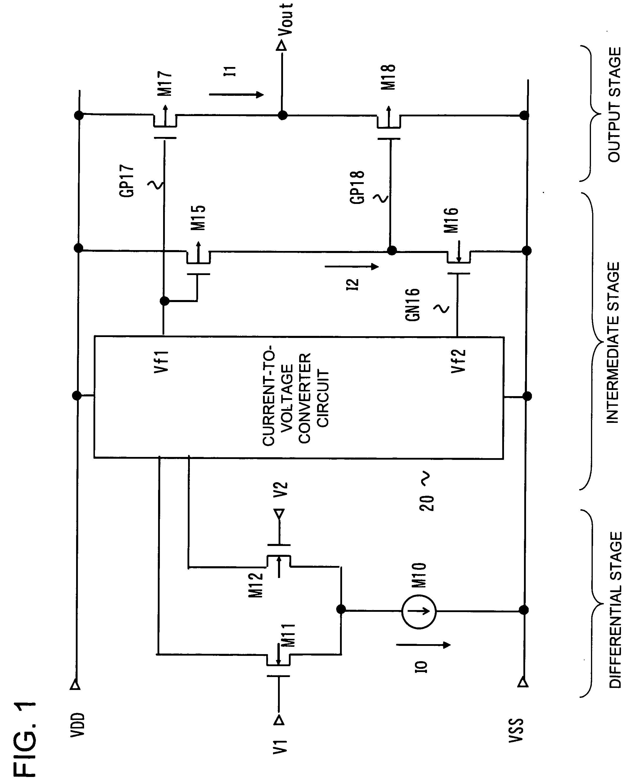
[0061]In order to describe the present invention described above in further detail, a description will be given with reference to appended drawings. FIG. 1 is a diagram showing a configuration of a first exemplary embodiment of the present invention. FIG. 1 shows a configuration of a differential amplifier used as a positive-polarity output buffer amplifier in FIG. 7.

[0062]Referring to FIG. 1, the differential amplifier includes:

[0063]a current source M10 which has one end connected to a terminal of a first power supply (VSS) constituted from a low-potential voltage supply;

[0064]NMOS transistors M11 and M12 which have coupled sources connected to the other end of the current source M10, MOS transistors M11 and M12 constituting a differential pair that differentially receive input signal voltages (V1, V2);

[0065]a current-to-voltage converter circuit 20 which is connected to outputs (drains) of the differential pair formed of the NMOS transistors M11 and M12, and performs current-to-v...


PUM


Abstract

Disclosed is a differential amplifier of the present invention includes a differential pair differentially receiving a signal, a current source connected between a first voltage supply and the differential pair, for driving the differential pair, a current-to-voltage converter circuit receiving output currents of the differential pair and producing first and second voltage signals, first and second transistors of mutually different conductivity types connected in series between the first voltage supply and a second voltage supply and respectively receiving the first and second voltage signals at control terminals thereof, a third transistor connected between the second voltage supply and an output terminal and receiving the first voltage signal at a control terminal thereof, and a fourth transistor of the same conductivity type as that of the third transistor, the fourth transistor being connected between the output terminal and the first voltage supply and having a control terminal thereof connected to a connecting node between the first and second transistors.

Description

REFERENCE TO RELATED APPLICATION [0001]This application is based upon and claims the benefit of the priority of Japanese patent application No. 2008-061781 filed on Mar. 11, 2008, the disclosure of which is incorporated herein in its entirety by reference thereto.FIELD OF THE INVENTION[0002]The present invention relates to a differential amplifier and a drive circuit of a display device using the differential amplifier.BACKGROUND ART[0003]In recent years, a demand for liquid crystal display devices for use in large-screen liquid crystal TV sets as well as for use in portable telephones (such as mobile phones or cellular phones), notebook PCs, and monitors has expanded. As these liquid crystal display devices, the liquid crystal display devices with an active matrix driving system that enables high-resolution display are used. First, a typical configuration of the liquid crystal display device with the active matrix driving system will be outlined with reference to FIG. 6. In FIG. 6,...

Claims


Application Information

Patent Timeline
IPC IPC(8): G09G5/00H03F3/45
CPCG09G3/3688G09G2310/0291H03F2203/45726G09G2330/021H03F3/45183G09G2310/0297
Inventor TSUCHI, HIROSHI
Owner RENESAS ELECTRONICS CORP
Why Eureka
Try Eureka