Single sensor multi-functional dental extra-oral x-ray imaging system and method

a dental x-ray imaging and multi-functional technology, applied in the field of panoramic computerized tomography dental x-ray imaging systems, can solve the problems of not being able to do transverse slices, adding significantly to the cost of the dentist, and the system is much more expensive for the doctor

Active Publication Date: 2009-09-17
OY AJAT LTD
View PDF17 Cites 44 Cited by
  • Summary
  • Abstract
  • Description
  • Claims
  • Application Information

AI Technical Summary

Benefits of technology

[0015]In accordance with a second aspect of the current invention, there is an extra-oral dental x-ray imaging system comprising an x-ray source exposing x-rays to an object to be imaged; an x-ray imaging device suitable for producing multiple frames during at least part of the exposure, the x-ray imaging device has an active area with a long dimension m and a short dimension n with m / n≧1.5 (one point five), manipulator for moving along a path the imaging device between consecutive radiated frames during exposure, the manipulator enabling movement of the x-ray source and the imaging device by means of selective translation and selective rotation about at least one rotational axis located between a focal point of the x-ray source and the x-ray imaging device; said extra-oral dental x-ray imaging system having an exposure profile program for producing a substantially linear projection of at least part of said object to be imaged said profile comprising at least two substantially linear sections. The linear projection is preferably a cephalometric image of the human skull.
[0020]The imaging device is of the type that is linear, with a long dimension m and a sort dimension n, such that m / n≧1.5, and more preferable m / n>3 and even more preferably m / n>6. The choice of the imaging device to be rectangular with elongated linear shape is very important because such imaging device (sensor) is able to operate at high frame rates of more than 50 frames per second (“fps”), more preferably more than 100 fps and even more preferably in the range of 150 fps to 500 fps. With an elongated, fast imaging device the current invention produces very high quality panoramic images (because of the high speed), while maintaining a low cost. Preferably the imaging device is a CdTe-CMOS (Cadmium Telluride—CMOS) or CdZnTe-CMOS (Cadmium Zinc Telluride). Such imaging device combines excellent detection efficiency and excellent resolution with high speed.
[0025]The panoramic images as well as the transverse (to the panoramic) images and skull linear projections are all of excellent quality, without compromising one or the other.
[0026]The system is much more compact than conventional high end panoramic systems with a ceph arm or dental CT systems.

Problems solved by technology

With the above in mind the extra oral system performing panoramic imaging the sensor is typically long and with a small width but does not produce any frames and is not capable of doing transverse slices.
Mostly orthodontists use the panoramic systems with or without the ceph arm, which is usefull but typically will add significantly to the cost for the dentist.
The addition of a second sensor makes the system much more expensive for the doctors.
Beyond the advanced pan systems, there exist the very expensive dental CT systems, with large area flat panels.
Furthermore the dental CT systems have the capability to produce all of the needed panoramic images and transverse slices and 3D volumes, but the quality of the basic or standard panoramic image is much worse than the quality of a panoramic image produced with a five times cheaper standard digital pan system.
The reason why the dental CT systems do not make good quality pan images is that the flat panels used are large in area with low frame rate speed which does not exceed 30 fps.
At that low speed, the CT system is not able to do a standard pan exposure and the images come out blurred.

Method used


Image

  • Single sensor multi-functional dental extra-oral x-ray imaging system and method
  • Single sensor multi-functional dental extra-oral x-ray imaging system and method
  • Single sensor multi-functional dental extra-oral x-ray imaging system and method

Examples


Embodiment Construction

[0055]Prior to discussing the preferred embodiments of the current invention, the prior art will be reviewed.

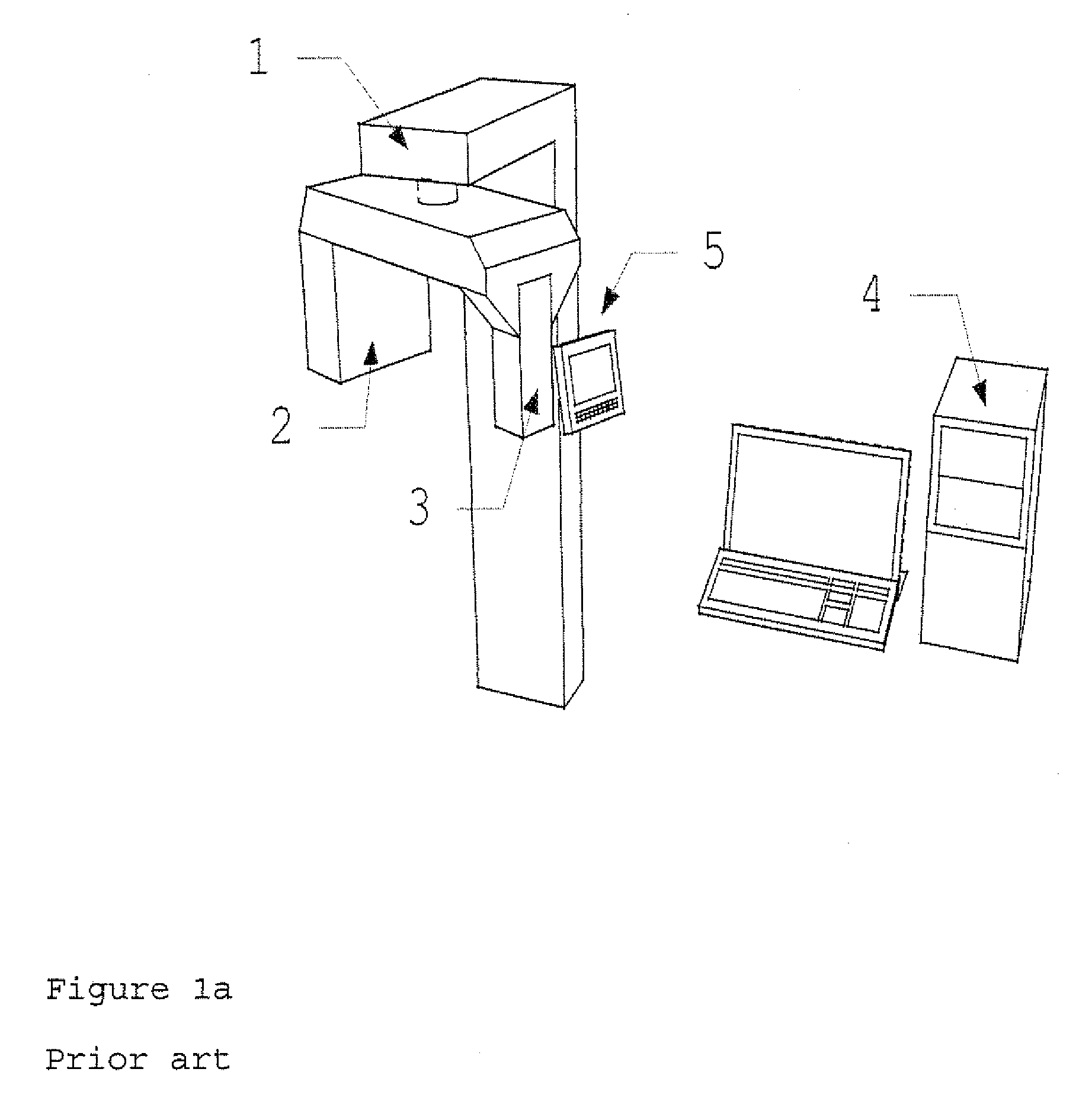
[0056]In FIG. 1a, a prior art standard panoramic x-ray imaging system is shown. A column (1) supports the pi shaped assembly with the x-ray tube (2) on one end and the CCD, line output CCD sensor (3) on the other. A manipulator inside the column (1) controls the movement of the assembly of the x-ray tube (2) and the CCD sensor (3). The manipulator usually comprises one or more motors. Normally, there are one or two motors and, in rarely, three motors. A control panel (5) is used to input the required x-ray exposure values (kV, mA) as well as choose the panoramic profile. The image is output, with a digital connection to a personal computer (4).

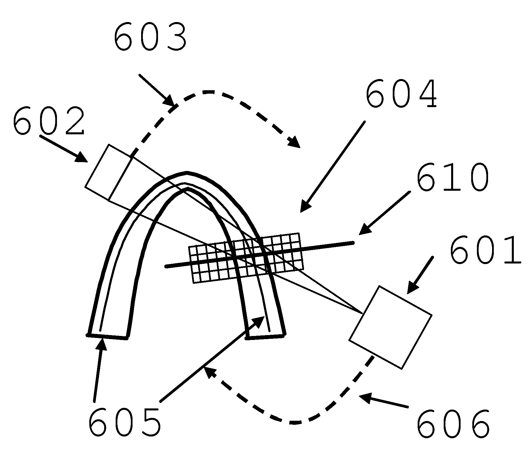
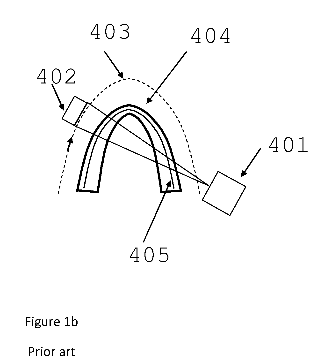
[0057]The components of a standard panoramic imaging profile in the prior art are illustrated in FIG. 1b. The x-ray source (401) and the imaging device (402), usually a CCD sensor, rotate and translate in order to produce an image of th...


PUM


Abstract

A multi-functional dental extra-oral x-ray imaging system includes a conventional x-ray source and manipulator to control the movement of the x-ray source by translating and rotating, a real time multiple frame producing x-ray imaging device and at least two different exposure profile programs, whereas one of such profiles produces a standard panoramic image and a second of such profiles produces an angled or transverse slice to a the panoramic image. A third exposure profile program produces a substantially linear projection of the human skull by combining two linear projections, one for the right and one for the left part of the head. The sensor is a linear direct conversion operating preferably in the frame mode and producing more than 100 fps.

Description

CROSS REFERENCE TO RELATED APPLICATIONS[0001]The present application claims the 35 U.S.C. §120 benefit of prior copending U.S. patent application Ser. No. 12 / 076,039 filed 13 Mar. 2008 which is incorporated herein by reference, and to which the present application is a continuation-in-part US national non-provisional utility patent application.BACKGROUND OF THE INVENTION[0002]The present invention relates to the field of dental extra-oral imaging systems. More specifically the present invention relates to panoramic dental x-ray imaging systems and Computerized Tomography (“CT”) dental x-ray imaging systems.DESCRIPTION OF THE RELATED ART[0003]Digital extraoral dental x-ray imaging systems can be divided into two main categories. The first category is planar imaging systems that produce a flat, two dimensional image. This category includes panoramic, transversal and cephalometric imaging. The second category consists of the so called volumetric imaging systems that produce three dimen...

Claims


Application Information

Patent Timeline
Patent Type & Authority Applications(United States)
IPC IPC(8): A61B6/14
CPCA61B6/14G06T11/006A61B6/588A61B6/4441
Inventor SPARTIOTIS, KONSTANTINOSPANTSAR, TUOMASLOHMAN, HENRIK VIKING
Owner OY AJAT LTD
Why Eureka
Try Eureka