Eureka AIR delivers breakthrough ideas for toughest innovation challenges, trusted by R&D personnel around the world.

Integrated Catalyst

Inactive Publication Date: 2009-09-17
BEKO TECHNOLOGIES GMBH +1
View PDF3 Cites 5 Cited by
  • Summary
  • Abstract
  • Description
  • Claims
  • Application Information

AI Technical Summary

Benefits of technology

[0011]It is the object of the present invention to provide an air compressor with a catalyst that reduces the oil contained in the compressed air to a very low amount. Thereby, as far as possible, the air compressor is intended to be at low cost to manufacture and to maintain. In particular, the apparatus should be of the smallest possible dimensions.
[0015]Through the proximity of the reception block to the compression chamber, the high temperatures anyway achieved by virtue of compression, are made use of for optimal operation of the catalyst. When air is being compressed, high compression temperatures of more than 300° C. occur due to the way the system operates, said temperatures being sufficient for the catalyst to react, so that additional heating is not necessary.
[0017]In particular, the integration of the catalyst in an air compressor with two cylinders in a water-cooled implementation as it is usually utilized in utility vehicles is readily possible. In air cooled machines it may also be readily inserted if the reception block is devised accordingly. In case of water cooling, the water channels existing in the cylinder are laid through the reception block so that the cooling flow needs not be interrupted.
[0022]The catalyst is pressed into a recess or a groove of the reception block that is adapted to the design of the substrate. During this pressing process, the catalyst is slightly deformed so that it is firmly retained in the recess or groove. A major advantage is that the discrete component parts must not be machined with the greatest possible accuracy; it is sufficient if it is molded for coarse registration fit, which is lower cost. The reception block is then mounted, together with the fixed catalyst, with corresponding gaskets between the valve block and the cylinder cover. As already discussed, other forms of the substrate may also be envisaged; instead of the foam-like cast metal one may also use a making with several plates which are cut to shape by means of water jet or laser and which are stacked one above the other in the receiving receptacle after coating. For passage of the compressed air, such type plates may for example be made from a grid material or a knit material. Another variant consists in using granulate as the catalyst material, which is also pressed into the receiving receptacle.

Problems solved by technology

The compressed gas is thereby almost inevitably contaminated with oil aerosols and oil vapor, all the more so if the air compressors are operated with oil lubrication.
For a plurality of applications, such type contamination is undesirable or even unacceptable.
Presently, no compressors are known which are capable of generating oil-free compressed gases without having to additionally process them.
The oil contaminates and, as a result thereof, affects the function of the components mounted downstream thereof.
Substantially, absorption filters made from activated carbon are known, but they have a short life.
Moreover, they must be disposed as additional components in the region of the air compressors, which means that they need space and mounting expense in accordance therewith.
In particular in case of smaller amounts of compressed air, such type oxidation catalysts are disproportionally expensive.
For this purpose, it is necessary to change the construction of the cylinder head or of the outlet channel since otherwise the quantity of oxidation catalyst material will not suffice.
Moreover, the oxidation catalyst is difficult to maintain or replace.
Finally, it seems unavoidable to rebuild the cylinder.

Method used


Image

  • Integrated Catalyst
  • Integrated Catalyst
  • Integrated Catalyst

Examples


Embodiment Construction

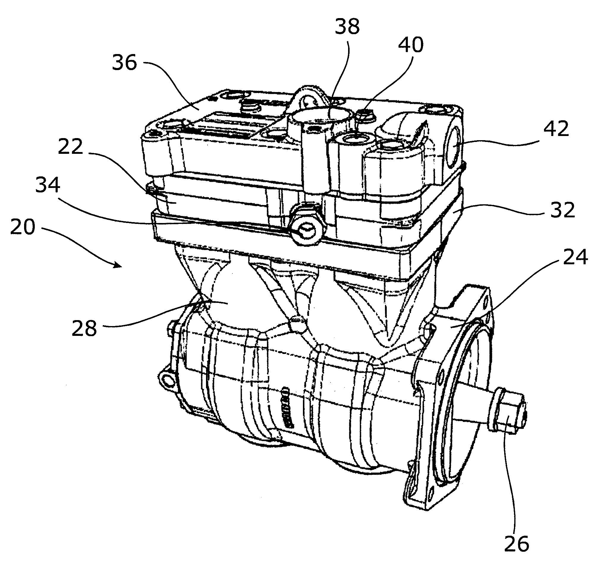
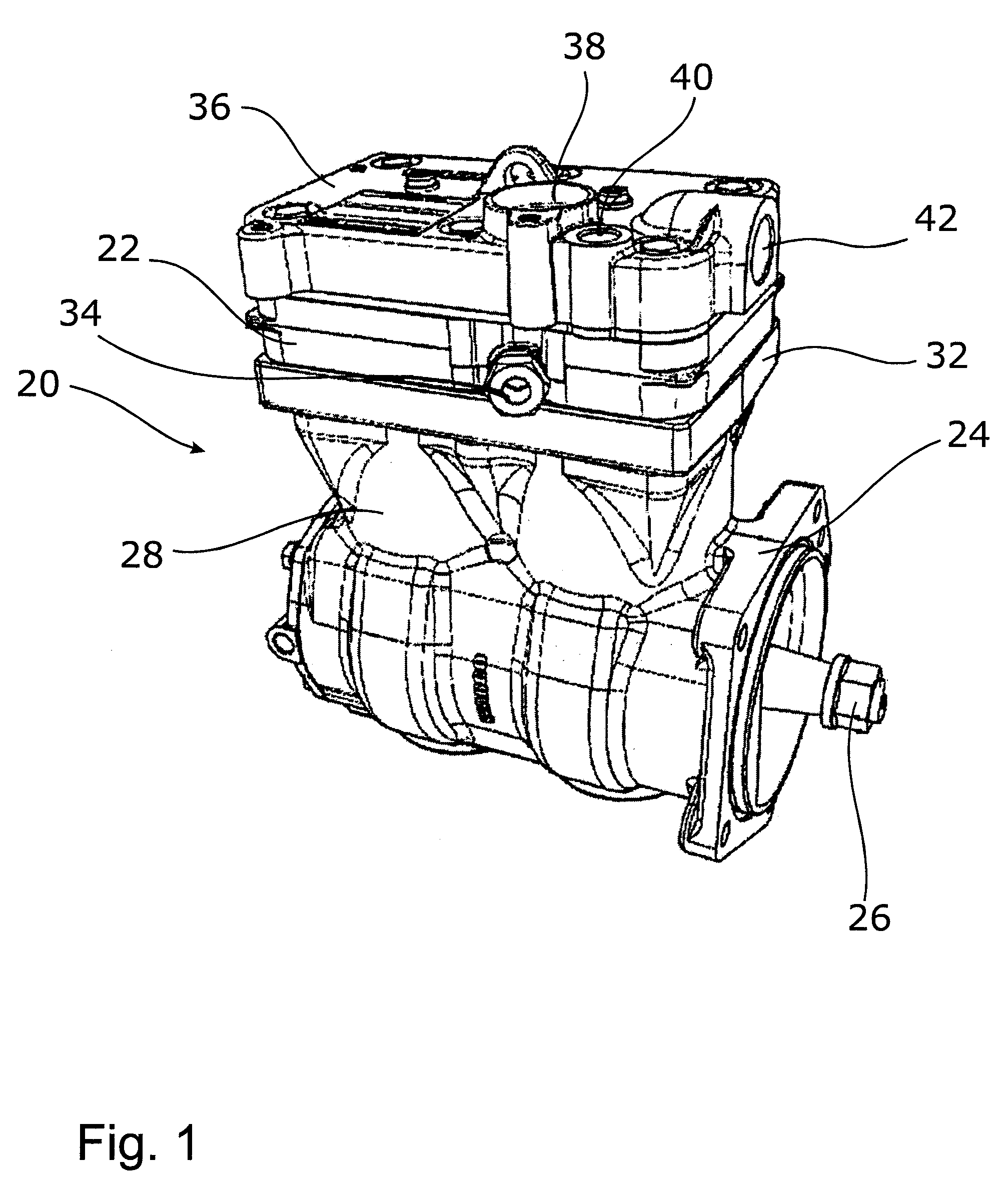
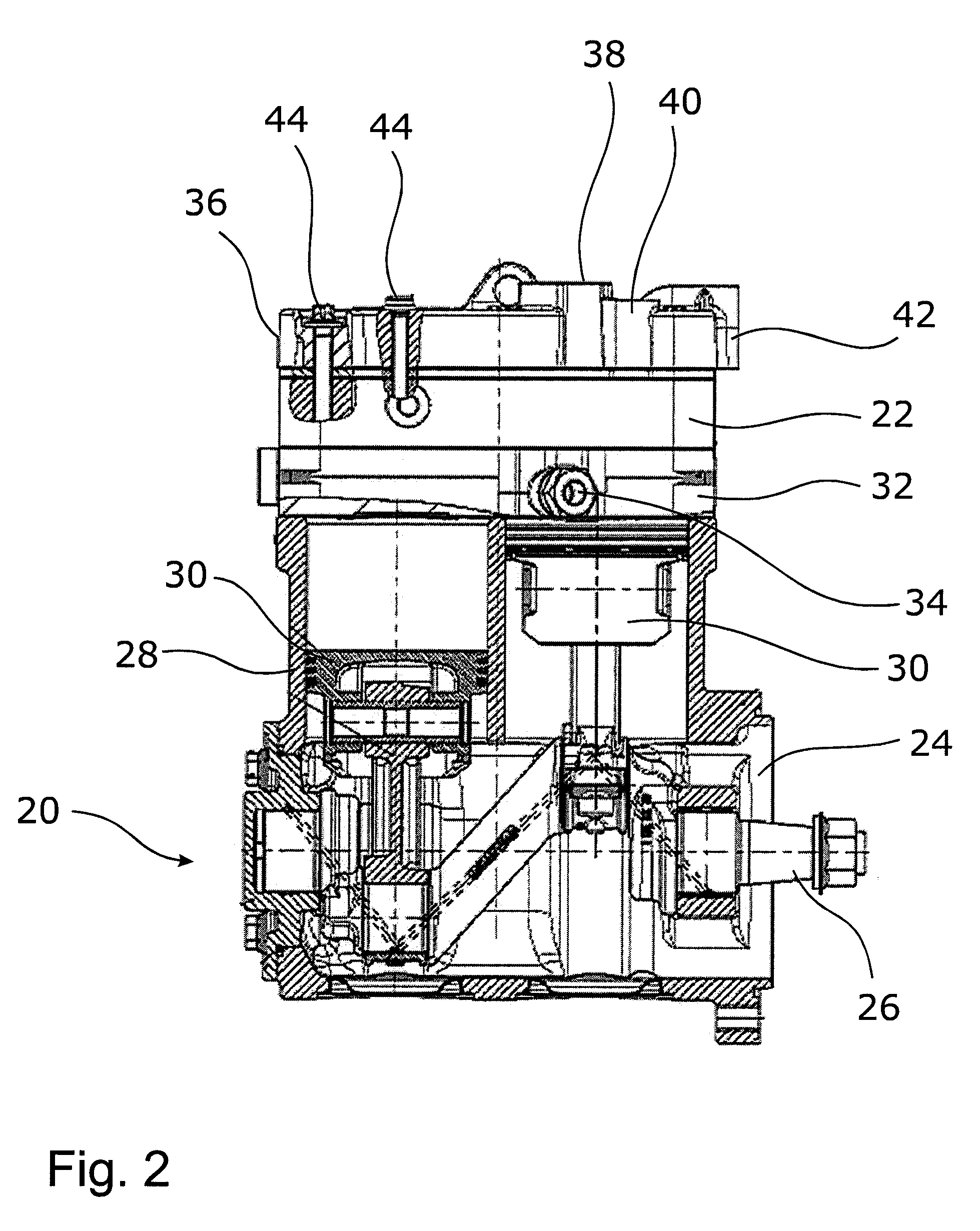
[0032]FIGS. 1 and 2 show an air compressor 20 of the invention, in which there is integrated a reception block 23. A piston compressor is shown by way of example. A crankcase 24 is adjoined with a drive shaft to a motor that has not been illustrated herein. The crankcase 24 is adjacent a cylinder block 28. Inside said cylinder block 28 there are located two pistons 30 in the exemplary embodiment shown. On the cylinder block28, there are further located a valve block 32 with a cooling water outlet 34. The reception block 22 is interposed between the valve block 32 and a cylinder cover 36, said cylinder cover 36 comprising an intake air inlet 38, a cooling water inlet 40 and a compressed air outlet 42. Further details of the air compressor 20 will not be discussed in closer detail herein since they correspond to commercially available air compressors for utility vehicles.

[0033]Advantageously, the reception block 22 is merely inserted between the cylinder cover 36 and the valve block 3...


PUM


Abstract

The invention relates to an air compressor having a catalyst that is disposed in a reception block. The reception block is interposed between a valve block and a cylinder cover, comprises an inlet port in the region of a valve block outlet port, and an outlet port in the region of a cylinder head inlet port, so the compressed air exiting the valve block outlet port flows through said catalyst and through the outlet port into the cylinder cover.

Description

CROSS-REFERENCE TO RELATED APPLICATIONS[0001]This patent application claims priority to co-pending German Patent Application No. DE 10 2008 014 205.0, filed Mar. 14, 2008, which is hereby expressly incorporated by reference in its entirety as part of the present disclosure.BACKGROUND OF THE INVENTION[0002]The present invention relates to an air compressor with a catalyst disposed in a reception block.[0003]Air compressors generate compressed air by drawing and compressing ambient air. They are utilized in the industry and often also on trucks in order to provide compressed air for the brake system or for the vehicle spring or damper system. The compressed gas is thereby almost inevitably contaminated with oil aerosols and oil vapor, all the more so if the air compressors are operated with oil lubrication. Due to the small amount of leakage between pistons and cylinders, the oil aerosols and the oil vapor are transported with the supplied compressed air into the compressed air system...

Claims


Application Information

Patent Timeline
IPC IPC(8): A61M1/00F04B25/00B01J19/00
CPCF04B39/12F04B39/16F04B39/125F04B39/121
Inventor AY, DOGANJORDAN, STEFFENSTUMBERG, INGOSCHLENSKER, HERBERT
Owner BEKO TECHNOLOGIES GMBH
Why Eureka
Eureka Blog
Learn More