Multiple carrier radio systems and methods employing polar active antenna elements

a radio system and antenna element technology, applied in the field of wireless communication, can solve the problems of inefficient mcpa 206, less efficient collective efficiency of the plurality, and very inefficient linear power amplifiers, and achieve the effects of substantially higher efficiency of multiple carrier radio methods and systems of the present invention, less power dissipation, and high power consumption of ac/d

Inactive Publication Date: 2009-09-17
PANASONIC CORP
View PDF22 Cites 16 Cited by
  • Summary
  • Abstract
  • Description
  • Claims
  • Application Information

AI Technical Summary

Benefits of technology

[0010]The multiple carrier radio systems and methods of the present invention have a number of significant advantages over prior art multi-carrier radio transmitter systems. First, the PAAE's employ nonlinear switch-mode PAs, rather than linear PAs. Consequently, the efficiency of the multiple carrier radio methods and systems of the present invention are substantially higher than prior art linear-PA-based approaches. Second, because the PAAE's used in the methods and systems of the present invention dissipate substantially less power compared to prior art linear-PA-based approaches, large air conditioning units and high power consuming AC / DC converters are not needed. Third, because RF power generation is performed up in the tower close to the antenna elements, and not on the ground as in prior art approaches, RF feed losses resulting from transferring RF power from the base of the BTS tower to the antenna elements are avoided. Fourth, because the systems and methods of the present invention use a plurality of PAs to generate multiple modulated RF carrier signals, the single point of failure problem caused by using only a single multi-carrier PA (MCPA) is avoided. Finally, but not necessarily lastly, high power consumption combiners are not needed to combine multiple RF carrier signals in the methods and systems of the present invention. Instead, in circumstances in which it is desired to combine RF carrier signals, the RF carrier signals are combined in space (i.e., spatially) after being radiated by the antennas of the PAAE's.

Problems solved by technology

While the multiple carrier BTS radio system 100 does succeed in transmitting multiple modulated RF carrier signals at the same time, from a power consumption perspective it does so very inefficiently.
Unfortunately, the MCPA 206 is less efficient than the collective efficiency of the plurality of PAs 104-1, 104-2, .
Unfortunately, linear power amplifiers are very inefficient, and results in the MCPA-based radio system 304 being very large and heavy.
In fact the MCPA-based radio system 304 is usually so large and heavy that it cannot, as a practical matter, be mounted in the BTS tower 310.
First, the MCPA-based radio system 304 presents a single point of failure, since it only employs a single PA.
Second, the requirement that the MCPA-based radio system 304 operate with high linearity results in large amounts of wasted power.
Not only is this wasted power costly, it is also harmful to the environment.
Third, because the MCPA-based radio system 304 is so inefficient and must be mounted on the ground, power is lost in the antenna feed 312 as the amplified multi-carrier signal at the output of the MCPA-based radio system 304 is conveyed to the passive antenna elements 314 mounted in the BTS tower 310.
Finally, due again to the inefficiency and size of the MCPA-based radio system 304, an expensive and power consuming air conditioning unit 308 is needed.

Method used


Image

  • Multiple carrier radio systems and methods employing polar active antenna elements
  • Multiple carrier radio systems and methods employing polar active antenna elements
  • Multiple carrier radio systems and methods employing polar active antenna elements

Examples


Embodiment Construction

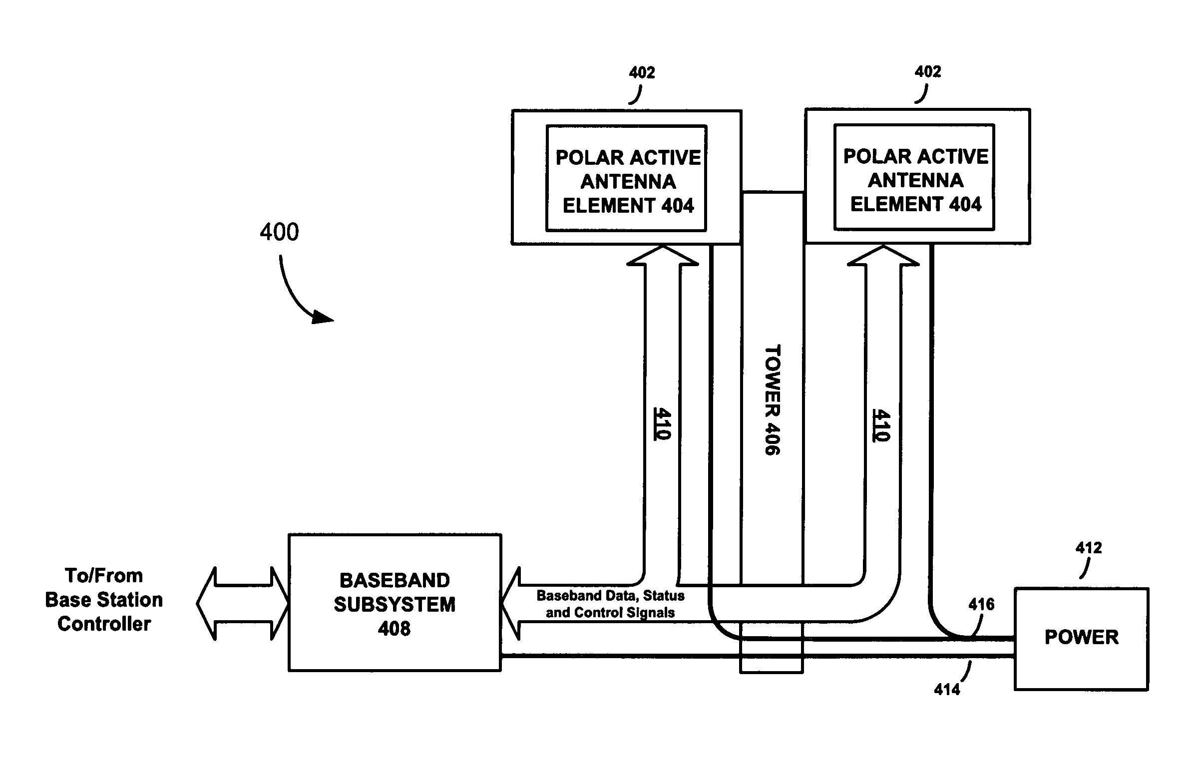
[0020]Referring to FIG. 4, there is shown a base transceiver station (BTS) 400 equipped with polar active antenna elements (PAAE's) 404, according to an embodiment of the present invention. The BTS 400 comprises a communications tower 406, upon which one or more radio frequency (RF) transceivers 402 having PAAE's 404 are mounted, and a baseband subsystem 408. A digital communications bus 410 comprising, for example, one or more fiber optic cables, is coupled between the RF transceivers 402 and the baseband subsystem 408 for conveying digital baseband data, status and control signals between the baseband subsystem 408 and the RF transceivers 402. A power source 412 provides power to the baseband subsystem 408 and to the RF transceivers 402 via power lines 414 and 416.

[0021]The baseband subsystem 408 of the BTS 400 is operable to send and receive digital messages to and from a base station controller (BSC) or mobile switching center. It may be placed in a cabinet or other protective h...


PUM


Abstract

A multiple carrier radio system includes a baseband subsystem and a plurality of polar modulators. The polar modulators are mounted at antenna locations (e.g., in a base transceiver station (BTS)) above the ground), and are configured to receive modulation signals generated by the baseband subsystem. The plurality of polar modulators generates a plurality of modulated RF carrier signals using the modulation signals. The modulated RF carrier signals are radiated by a corresponding plurality of antenna elements coupled to the plurality of polar modulators.

Description

FIELD OF THE INVENTION[0001]The present invention relates to wireless communications. More specifically, the present invention relates to the generation and transmission of multiple modulated radio frequency carrier signals in wireless communications networks.BACKGROUND OF THE INVENTION[0002]A cellular communications network includes geographically dispersed base transceiver stations (BTSs) that provide an interface between cellular handsets and the network. To limit the number of BTSs that must be built and maintained in the network, the BTSs are equipped with radio systems that handle multiple calls at the same time. Traditionally, this has been accomplished by employing a multiple carrier BTS radio system 100 like that shown in FIG. 1. The multiple carrier BTS radio system 100 includes a plurality of transceivers (TX1, TX2, . . . , TX ) 102-1, 102-2 . . . 102-m (m is an integer that is ≧2), an associated plurality of linear power amplifiers (PAs) 104-1, 104-2, . . . , 104-m, a co...

Claims


Application Information

Patent Timeline
Patent Type & Authority Applications(United States)
IPC IPC(8): H04B1/38H04B1/02
CPCH04B1/0483H04L27/2601H04L5/0023
Inventor MCCUNE, JR., EARL W.
Owner PANASONIC CORP
Why Eureka
Try Eureka