Eureka AIR delivers breakthrough ideas for toughest innovation challenges, trusted by R&D personnel around the world.

Process for producing latent catalyst and epoxy resin composition

a technology of epoxy resin and latent catalyst, which is applied in the field of preparation of latent catalyst and epoxy resin composition, can solve the problems of mold defects, inability to solve (dealt with) conventional epoxy resin composition, and high demand for epoxy resin compositions to be used in encapsulating semiconductor chips therewith. , to achieve the effect of excellent fluidity, high yield and excellent curing properties

Inactive Publication Date: 2009-09-17
SUMITOMO BAKELITE CO LTD
View PDF12 Cites 12 Cited by
  • Summary
  • Abstract
  • Description
  • Claims
  • Application Information

AI Technical Summary

Benefits of technology

This patent describes how to make a new type of chemical called a latent catalyst that helps accelerate the curing of epoxy resin. By making this catalyst in a certain way, we are able to get a higher yield than other methods. When used in epoxy resin compositions, this catalyst gives them better flowability (how easy they spread), longer shelf life, and faster curing times.

Problems solved by technology

The technical problem addressed in this patent is how to improve the properties of epoxy resin compositions used in encapsulating semiconductor chips while maintaining their fluidity during manufacturing processes. Current methods involve adding excessive amounts of inorganic fillers to enhance rapid curability but these cause issues like reduced flexibility and decreased reliability. To solve this issue, researchers have developed curing accelerators called onium salts with a chelate structure that show promising results in terms of both curing and fluidity. However, existing synthetic techniques lead to difficulties in achieving high purity and yields of the final products.

Method used


Image

  • Process for producing latent catalyst and epoxy resin composition
  • Process for producing latent catalyst and epoxy resin composition
  • Process for producing latent catalyst and epoxy resin composition

Examples


example 1

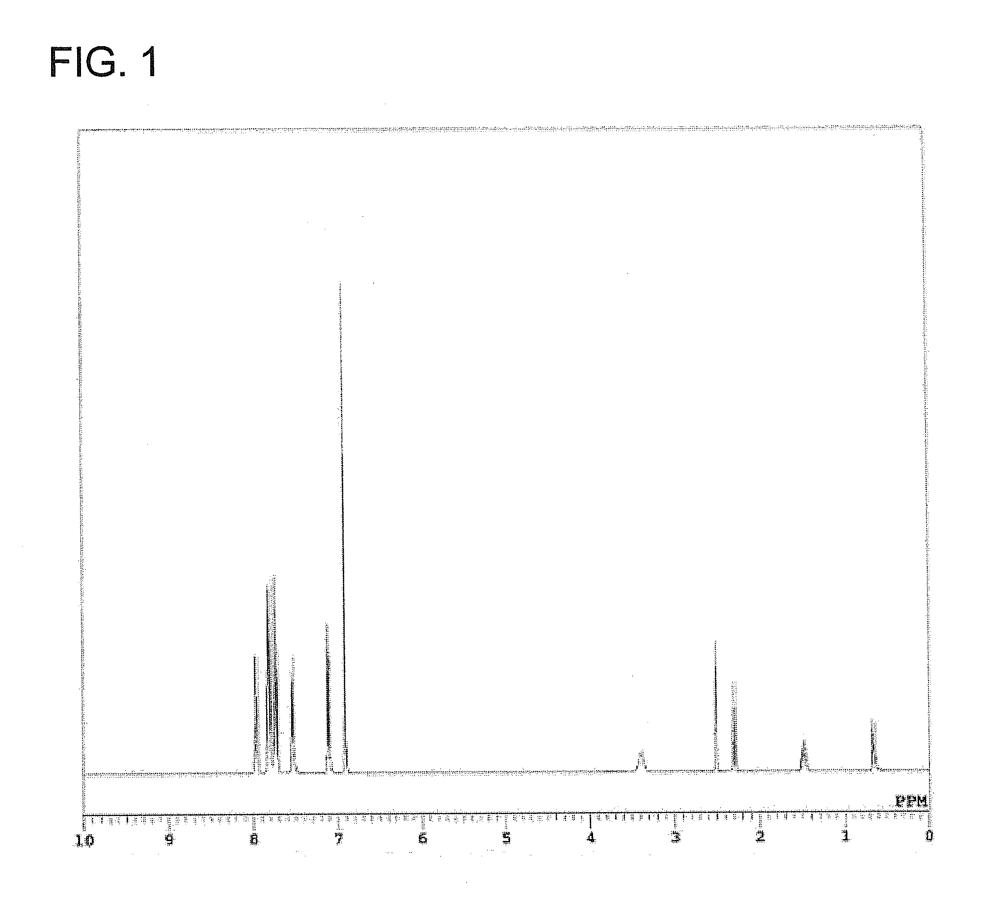
[0085]In a separable flask (volume: 500 mL) equipped with a condenser and a stirrer were charged 32.0 g (0.20 mol) of 2,3-dihydroxynaphthalene, 19.6 g (0.10 mol) of 3-mercaptopropyltrimethoxysilane and 150 mL of ethanol and they were dissolved uniformly under stirring. A solution obtained in advance by dissolving 5.40 g (0.10 mol) of sodium methoxide in 20 mL of ethanol was added dropwise into the flask under stirring. Another solution obtained in advance by dissolving 41.9 g (0.10 mol) of tetraphenylphosphonium bromide in 100 mL of ethanol was then gradually added dropwise into the flask to precipitate crystals. The crystals thus precipitated were purified by filtration, washing with water and vacuum drying, whereby Compound G1 was obtained.

[0086]Compound G1 was analyzed by 1H-NMR, mass spectrum and elemental analysis. It has been confirmed by the analysis results that Compound G1 thus obtained was phosphonium silicate represented by the below-described formula (7) The yield of Com...

example 2

[0087]Synthesis was performed in the same manner as in Example 1, except that 23.6 g (0.10 mol) of 3-glycidyloxypropyltrimethoxysilane was used in place of 3-mercaptopropyltrimethoxysilane, whereby Compound G2 was obtained as purified crystals. Compound G2 was analyzed by 1H-NMR, mass spectrum and elemental analysis. It has been confirmed by the analysis results that Compound G2 thus obtained was phosphonium silicate represented by the below-described formula (8). The yield of Compound G2 was 88%.

example 3

[0088]Synthesis was performed in the same manner as in Example 1, except that 43.5 g (0.10 mol) of 3-hydroxyphenyltriphenylphosphonium bromide was used in place of tetraphenylphosphonium bromide, whereby Compound G3 was obtained as purified crystals. Compound G3 was analyzed by 1H-NMR, mass spectrum and elemental analysis. It has been confirmed by the analysis results that Compound G3 thus obtained was phosphonium silicate represented by the below-described formula (9). The yield of Compound G3 was 89%.


PUM

PropertyMeasurementUnit
Fractionaaaaaaaaaa
Catalytic activityaaaaaaaaaa
Fluidityaaaaaaaaaa

Abstract

An object of the invention is to provide a preparation process of a latent catalyst that can gives a latent catalyst, which can exert an excellent catalytic activity at the time of molding and therefore, can provide a resin composition having good curing property, fluidity and storage stability, in a short time in a high yield without mixing in ionic impurities. The present invention relates to a preparation process of a phosphonium silicate latent catalyst, comprising reacting (A) a proton donor represented by the following formula (1):
[Chemical Formula 1]
HY1-Z1-Y2H  (1)
[wherein Y1 and Y2 may be the same or different and each represents a group resulting from a proton donating substituent through release of a proton, Z1 represents a substituted or unsubstituted organic group which bonds to the proton donating substituents Y1H and Y2H, and two substituents Y1 and Y2 in the same molecule are capable of bonding to a silicon atom to form a chelate structure], (B) a trialkoxysilane compound and (D) a phosphonium salt compound represented by the following formula (2):
[wherein R1, R2, R3 and R4 may be the same or different and each represents an organic group having a substituted or unsubstituted, aromatic or heterocyclic ring or represents a substituted or unsubstituted aliphatic group and X represents a halide ion, a hydroxide ion or an anion resulting from a proton donating group through release of a proton], wherein the reaction is carried out in the presence of (C) a metal alkoxide compound.

Description


Claims


Application Information

Patent Timeline
Owner SUMITOMO BAKELITE CO LTD
Why Eureka
Eureka Blog
Learn More