
Torque control method for hybrid electric vehicle

a hybrid electric vehicle and torque control technology, applied in hybrid vehicles, dynamo-electric converter control, motor/generator/converter stoppers, etc., can solve the problems of increased risk of accidents, deterioration of driving performance, and difficulty in engine start-up, so as to reduce the hydraulic pressure of the clutch

Active Publication Date: 2009-09-17
HYUNDAI MOTOR CO LTD +1
View PDF17 Cites 51 Cited by
  • Summary
  • Abstract
  • Description
  • Claims
  • Application Information

AI Technical Summary

Benefits of technology

[0018]In a preferred embodiment, the process of controlling the hydraulic pressure and operation of the clutch comprises: feedback controlling the hydraulic pressure of the clutch to cause clutch slip; increasing the engine speed to an injection RPM through the clutch slip and then rel

Problems solved by technology

If the driver's intention is not sufficiently reflected in calculating the driver demand torque, the vehicle may be driven against the driver's intention, which may result in a deterioration of driving performance and an increase in the risk of an accident.
However, in the event of failure of the ISG 40, the engine start-up is not easy.
Although the engine start-up is available by clutch slip (friction start) in the above state, the driving performance may be deteriorated and further the acceleration performance of the vehicle may be deteriorated.
However, the method only aims at starting up the engine by hydraulic profile modeling of the engine clutch, and drag generated by a transfer torque of the engine clutch during start-up is not compensated, thus deteriorating the driving performance and acceleration performance of the vehicle.
However, the method has the same drawback in that the drag generated by the transfer torque of the clutch is not compensated.

Method used


Image

  • Torque control method for hybrid electric vehicle
  • Torque control method for hybrid electric vehicle
  • Torque control method for hybrid electric vehicle

Examples


first embodiment

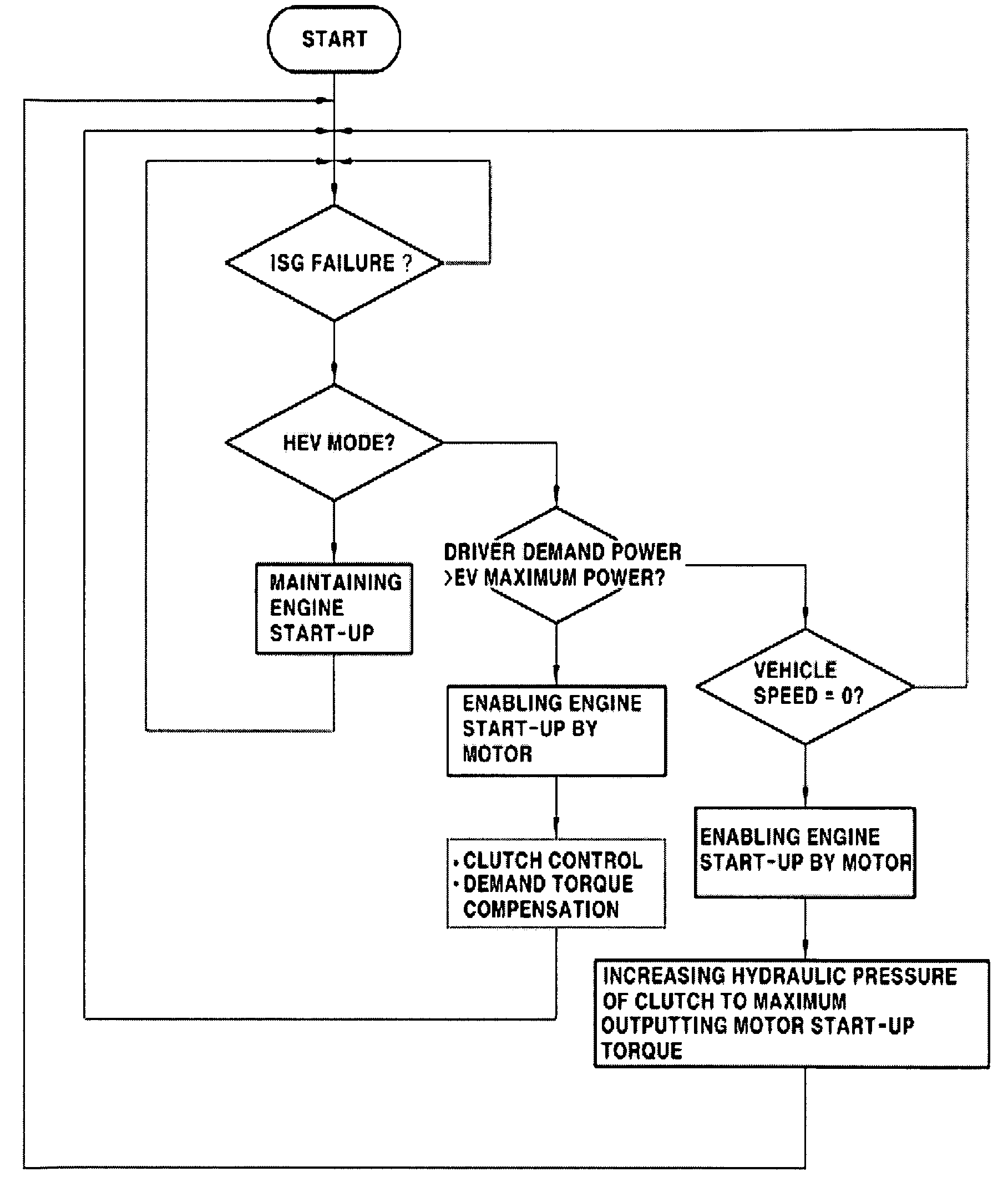
[0046]Referring to FIG. 4, the control method is described. First, the hydraulic pressure of the clutch is feedback controlled to cause clutch slip. That is, the hydraulic pressure of the clutch is feedback controlled so as not to exceed the maximum hydraulic pressure to cause friction start by the clutch slip.

[0047]Then, the engine speed is increased to an injection RPM through the clutch slip, and the hydraulic pressure of the clutch is reduced to release the engagement of the clutch. In more detail, the hydraulic pressure is applied against the force of a return spring included in the clutch before the fuel injection into the engine is performed until the rotational speeds of both sides of the clutch connecting the engine and the motor are synchronized with each other, thus releasing the engagement of the clutch.

[0048]Subsequently, after releasing the engagement of the clutch, the fuel injection operation of the engine is performed. Next, after the fuel injection operation of the...

second embodiment

[0052] since only the clutch slip control is performed until the clutch engagement (full lock-up), it is possible to facilitate the control without any additional sequence and the mode conversion to the HEV mode is promptly made. Moreover, since the engine injection is rapidly initiated through the clutch slip, it is possible to significantly reduce the clutch slip time, thus maintaining the durability of the clutch.

[0053]Meanwhile, the driver demand torque compensation, in which the driver demand torque is compensated based on the transfer torque from the clutch to the motor during the clutch slip, is performed the same manner as the first embodiment, and its description will be given in detail later.

[0054]Referring to FIG. 6, a third embodiment of the control method is described. First, the hydraulic pressure of the clutch is feedback controlled to cause the clutch slip in the same manner as the first and second embodiments. The engine speed is increased to the injection RPM throu...

third embodiment

[0055] since only the clutch slip control is performed until the clutch engagement (full lock-up), it is possible to facilitate the control without any additional sequence and the mode conversion to the HEV mode is promptly made. Especially, since the engine injection is not performed during the clutch slip, it is possible to prevent the engine torque from changing abruptly in a state where the clutch is not completely engaged.

[0056]Meanwhile, the driver demand torque compensation, in which the driver demand torque is compensated based on the transfer torque from the clutch to the motor during the clutch slip, is performed the same manner as the first and embodiments, and its description will be given in detail below.

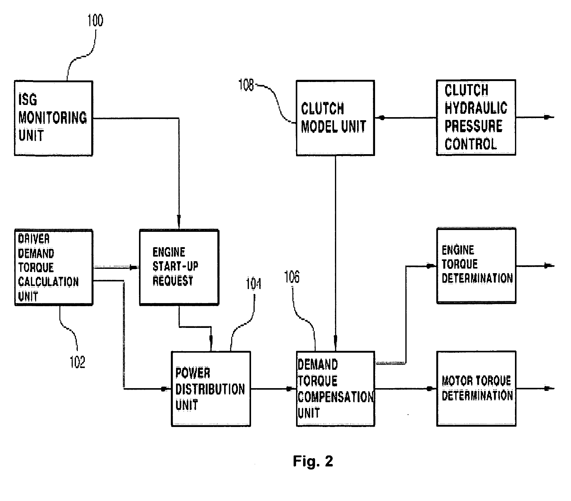
[0057]The process of compensating the driver demand torque will be described in detail below. As described in the above respective embodiments, during the clutch slip operation, the compensation for the driver demand torque, in which the transfer torque from the clutch ...


PUM


Abstract

The present invention provides a torque control method for an HEV, the method comprising: detecting an operation failure of an integrated starter-generator (ISG); calculating a driver demand torque based on a current accelerator position sensor (APS); controlling the hydraulic pressure and operation of a clutch so as to increase an engine speed to convert the driving mode of the vehicle from electric vehicle (EV) mode to hybrid electric vehicle (HEV) mode in the event that an operation failure of the ISG is detected and the driver demand torque is out of a predetermined range; and compensating the driver demand torque to a desired level based on a transfer torque from the clutch to a motor. The method can improve driving performance and power performance of HEV, in the event of ISG failure, by performing a hydraulic control for a clutch and calculating a driver request torque and a transfer torque from the clutch to a motor to compensate the drive request torque to a desired level.

Description

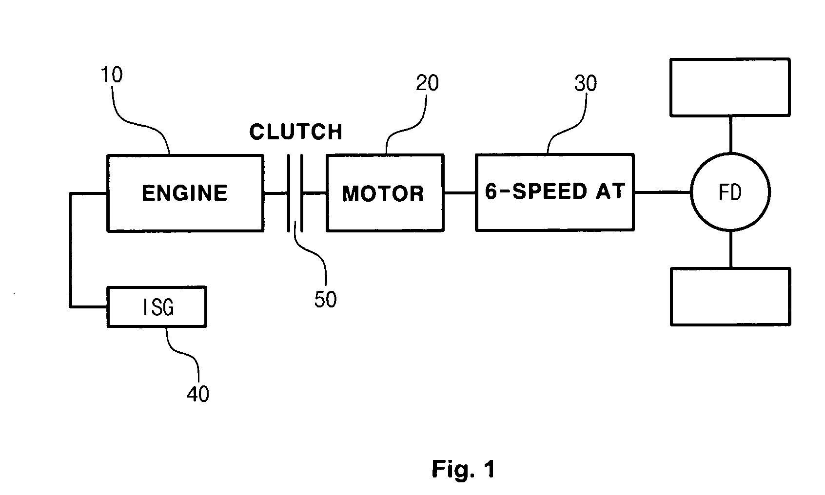
CROSS-REFERENCE TO RELATED APPLICATION[0001]This application claims under 35 U.S.C. §119(a) the benefit of Korean Patent Application No. 10-2008-0023610 filed Mar. 14, 2008, the entire contents of which are incorporated herein by reference.BACKGROUND[0002](a) Technical Field[0003]The present invention relates to a torque control method for a hybrid electric vehicle (HEV), which can improve driving performance and power performance, in the event of integrated starter-generate (ISG) failure, by performing a hydraulic control for a clutch and calculating a driver request torque and a transfer torque from the clutch to a motor to compensate the drive request torque to a desired level.[0004](b) Background Art[0005]A hybrid electric vehicle (HEV) employs a motor drive source as an auxiliary power source as well as an internal combustion engine to provide a reduction in exhaust gas and an improvement in fuel efficiency. As shown in FIG. 1, the HEV has a structure in which an engine 10, a m...

Claims


Application Information

Patent Timeline
IPC IPC(8): G06F17/00
CPCB60K6/48Y10T477/38B60L2240/486B60W10/02B60W10/06B60W10/08B60W20/00B60W50/029B60W2540/10B60W2710/0644B60W2710/083B60W2710/105Y02T10/6221Y02T10/6286Y02T10/642Y02T10/48Y10T477/688Y10T477/26Y10T477/755B60L2240/423Y02T10/40Y02T10/62Y02T10/64B60K2006/268B60K6/26B60W20/50
Inventor KIM, SANG JOON
Owner HYUNDAI MOTOR CO LTD
Learn More