Non-Finite Element Implementation of the Finite Element Projection in Two Dimensions

a finite element and projection technology, applied in the field of non-finite element implementation of the finite element projection in two dimensions, can solve the problems of not being able to faithfully fit the real nozzle wall of the discretized computational domain, not being able to accurately communicate with the surface tension aspects of the fluid flow, and performing fairly well. , to achieve the effect of small bandwidth, less computing resources, and reduced time duration

Inactive Publication Date: 2009-09-17
SEIKO EPSON CORP
View PDF20 Cites 5 Cited by
  • Summary
  • Abstract
  • Description
  • Claims
  • Application Information

AI Technical Summary

Benefits of technology

[0009]Embodiments of the present invention provide a finite difference method, a finite element projection, and a non-finite-element implementation of the finite element projection for solving the incompressible continuity equation on quadrilateral grids to obtain pressure and fluid velocity. An exemplary apparatus for simulating and analyzing the flow of an incompressible fluid is also provided. More particularly, embodiments of the present invention provide a non-finite-element-method (non-FEM) to implement the finite element projection to obtain a linear system whose coefficient matrix has an average bandwidth of five, in comparison to the finite difference scheme using conventional finite element projection and implementation with a bandwidth of nine. A two-dimensional-five-point-stencil-based discretization is formulated to enforce the incompressible continuity equation. A shape function that is different from a weighting function used in the incompressible continuity equation is utilized to guarantee the five-point-stencil discretization is possible. The smaller bandwidth of the non-FEM scheme requires less computing resources and can compute the results in a reduced time duration, due to the simpler matrix to solve.

Problems solved by technology

VOF performs fairly well with regard to mass conversation but is not so accurate on surface tension aspects of fluid flow, especially when the ink droplet is smaller than 5 pico liters.
Since the wall of the narrowing section of the modeled nozzle is not parallel to any coordinate axis, the discretized computational domain cannot faithfully fit the real nozzle wall.
While a non-square (or non-rectangular) quadrilateral grid like the one in FIG. 3 can be naturally handled in finite element analysis, performing a finite difference analysis on such a grid is very difficult.

Method used


Image

  • Non-Finite Element Implementation of the Finite Element Projection in Two Dimensions
  • Non-Finite Element Implementation of the Finite Element Projection in Two Dimensions
  • Non-Finite Element Implementation of the Finite Element Projection in Two Dimensions

Examples


Embodiment Construction

[0028]In the following description, numerous specific details are set forth in order to provide a thorough understanding of the present invention. However, it will be apparent to those skilled in the art that the present invention may be practiced without some of these specific details. In other instances, well known process operations and implementation details have not been described in detail in order to avoid unnecessarily obscuring the invention.

I. Introduction

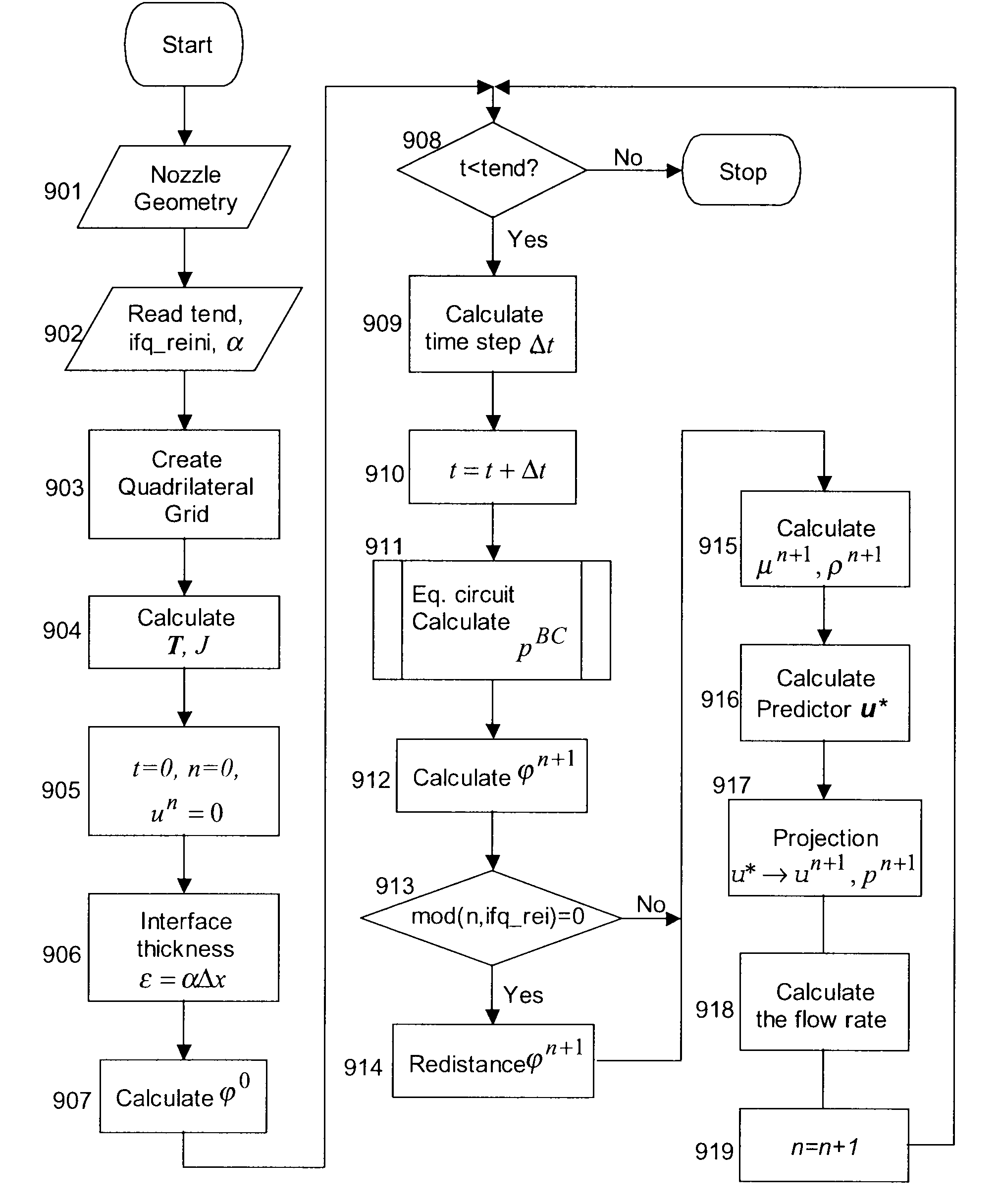
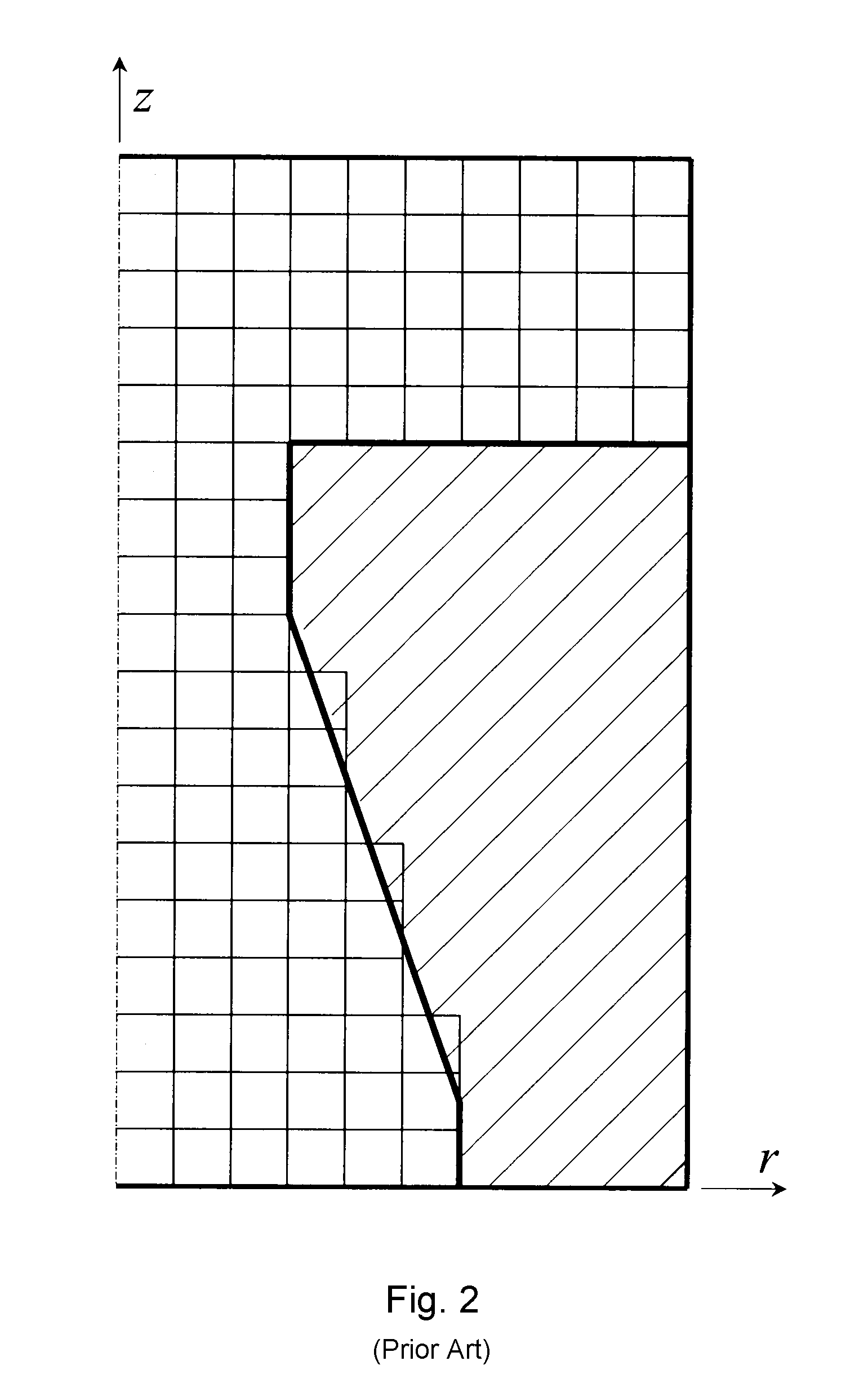
[0029]The model of this invention includes a quadrilateral grid for finite-difference-based ink-jet simulation. An accompanying algorithm is designed to solve the coupled Navier-Stokes equations and level set equations for two-phase flows that have been newly developed on the quadrilateral grid.

[0030]Governing partial differential equations, including the viscosity term, the surface tension term, and the level set convection equation for two-phase flows, are derived on the quadrilateral grid. A discrete transformation (ma...


PUM


Abstract

Embodiments of the present invention provide a finite difference method, a finite element projection, and a non-finite-element implementation of the finite element projection for solving the incompressible continuity equation on quadrilateral grids to obtain pressure and fluid velocity. An exemplary apparatus for simulating and analyzing the flow of an incompressible fluid is also provided. More particularly, embodiments of the present invention provide a non-finite-element-method (non-FEM) to implement the finite element projection to obtain a linear system whose coefficient matrix has an average bandwidth of five, in comparison to the finite difference scheme using conventional finite element projection and implementation with a bandwidth of nine. A two-dimensional-five-point-stencil-based non-FEM discretization is formulated to enforce the incompressible continuity equation. A shape function that is different from a weighting function used in the incompressible continuity equation is utilized to guarantee the five-point-stencil discretization is possible. The smaller bandwidth of the non-FEM scheme requires less computing resources and can compute the results in a reduced time duration, due to the simpler matrix to solve.

Description

CROSS REFERENCE TO RELATED APPLICATION[0001]This application is related to U.S. Pat. No. 7,117,138, filed on Mar. 14, 2003 and entitled “Coupled Quadrilateral Grid Level Set Scheme For Piezoelectric Ink-Jet Simulation,” and U.S. Pat. No. 7,085,695, filed on Mar. 22, 2002 and entitled “A Slipping Contact Line Model and the Mass-Conservative Level Set Implementation for Ink-Jet Simulation.” Both related applications are incorporated herein by reference.BACKGROUND[0002]1. Field of the Invention[0003]The present invention relates to a model and accompanying algorithm to simulate and analyze ink ejection from a piezoelectric print head. More particularly, the model of this invention includes a quadrilateral grid for finite-difference-based ink-jet simulation where the algorithm is designed to solve a set of partial differential equations for two-phase flows that have been newly developed on the quadrilateral grid. The quadrilateral grid is transformed to a uniform square grid, and the de...

Claims


Application Information

Patent Timeline
Patent Type & Authority Applications(United States)
IPC IPC(8): G06F9/455
CPCG06F2217/16G06F17/5018G06F30/23G06F2111/10
Inventor YU, JIUN-DER
Owner SEIKO EPSON CORP
Why Eureka
Try Eureka