Susceptor for vapor phase epitaxial growth device

a growth device and vapor phase technology, applied in the direction of chemically reactive gases, coatings, crystal growth processes, etc., can solve the problems of releasing gases that cannot be the same, the flatness of the wafer declines, and the clearance size between the wafer and the pocket becomes uneven, so as to prevent the wafer from skidding

Active Publication Date: 2009-09-24
SUMCO CORP +1
View PDF6 Cites 19 Cited by
  • Summary
  • Abstract
  • Description
  • Claims
  • Application Information

AI Technical Summary

Benefits of technology

[0012]An object of the present invention is to provide a susceptor for a vapor phase epitaxial growth device capable of enab...

Problems solved by technology

However, when a growth reaction of an epitaxial film is performed in a state that the center of the wafer is deviated from the center of the wafer pocket, a clearance size between the wafer and the wafer pocket becomes uneven in the circumferential direction and, thereby, flatness of the wafer declines; that has been a disadvantage.
However, it was found that, when dropping a wafer with super flatness on a susceptor having a h...

Method used


Image

  • Susceptor for vapor phase epitaxial growth device
  • Susceptor for vapor phase epitaxial growth device
  • Susceptor for vapor phase epitaxial growth device

Examples


first embodiment

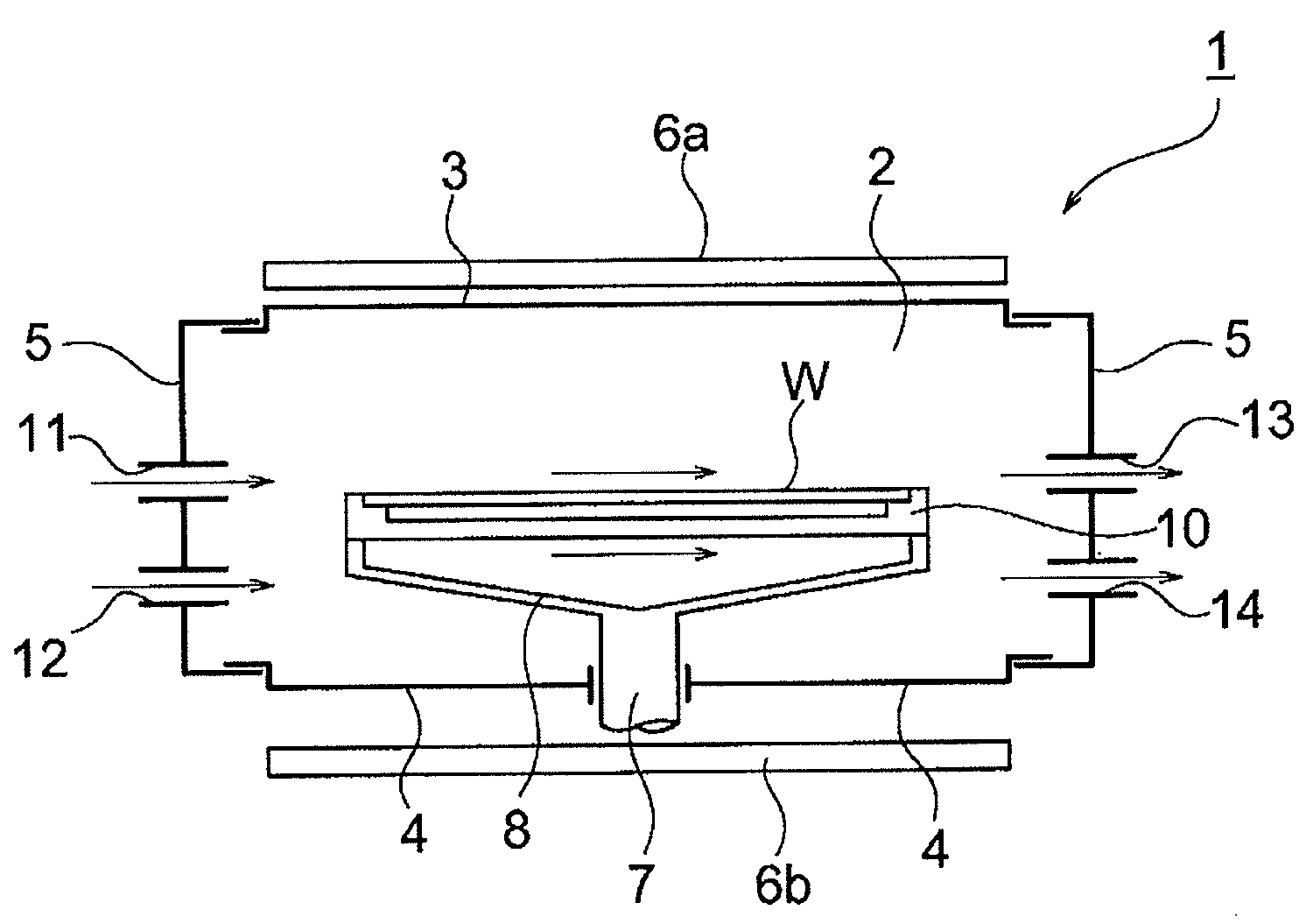
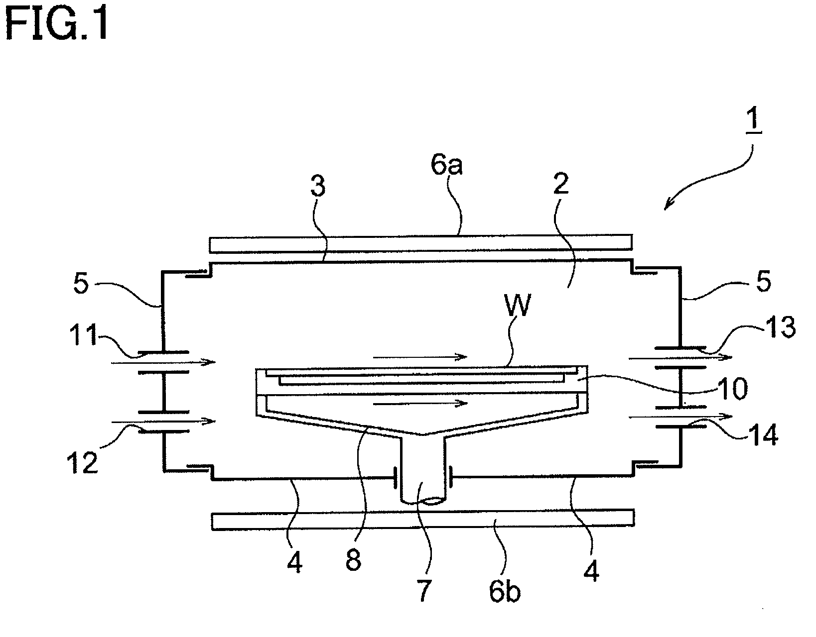
[0036]FIG. 1 is a schematic sectional view showing a single wafer vapor phase epitaxial growth device 1 for growing an epitaxial film on a surface of a silicon wafer W (hereinafter, also simply referred to as a wafer W), wherein an epitaxial film forming chamber 2 formed by attaching an upper dome 3 and a lower dome 4 to a dome mount 5 is provided. The upper dome 3 and the lower dome 4 are formed by a transparent material, such as quartz, and a susceptor 10 and a wafer W are heated by a plurality of halogen lamps 6a and 6b as heat sources arranged above and below the device 1.

[0037]The susceptor 10 is supported at its outer circumferential portion of a lower surface thereof by fitting with a support arm 8 connected to a rotation axis 7 and rotated by driving the rotation axis 7. A material of the susceptor 10 is not particularly limited and, for example, a carbon base material coated with a SiC film thereon is preferably used. A shape thereof will be explained later on.

[0038]Note th...

example 1

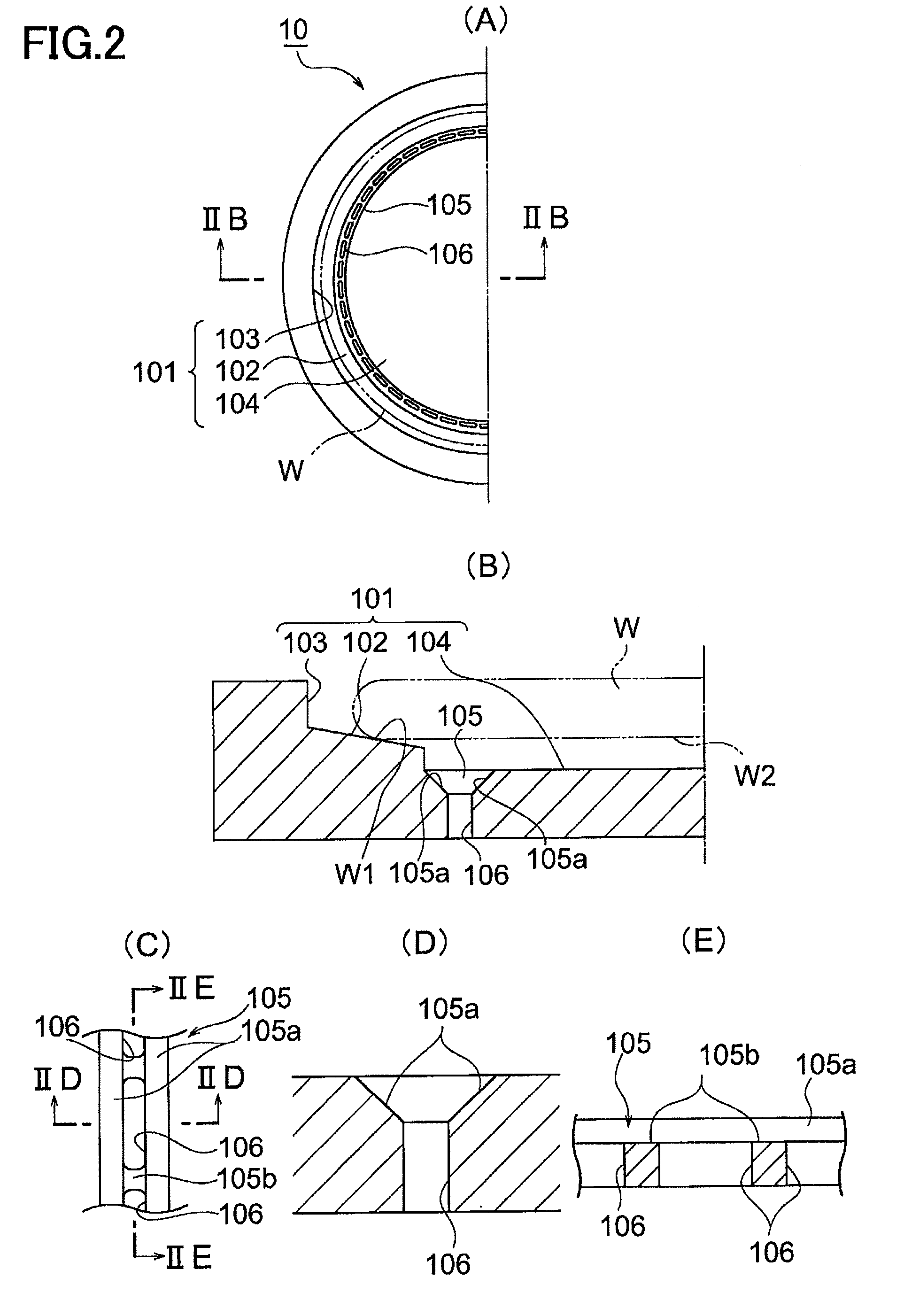
[0068]In a susceptor having the configuration as shown in FIG. 2, a diameter of the bottom surface was changed to 297 mm, a size of each gas release opening to 2.5 mm lengthwise×0.8 mm crosswise (opening area of 2.0 mm2), and the opening area ratio of the gas release openings to 0.25%, so that a silicon wafer having a diameter of 300 mm can be loaded.

[0069]The ring-shaped groove 105 was formed to be one row on the outermost circumference of the bottom surface 104, wherein the bottom portion 105b has two sloping planes 105a formed on both sides thereof and the gas release openings 106 were formed on the bottom surface of the ring-shaped groove 105 by the number of 130.

[0070]A hundred of silicon wafers having a diameter of 300 mm were loaded on the susceptor by supporting the lower surface of each wafer by pins and lowering the pins to place the wafer in the wafer pocket 101 from above the susceptor 10. An amount of deviation of the center of the wafer from the center of the wafer poc...

example 2

[0071]Other than changing the opening area ratio of the gas release openings to 0.5%, a susceptor was manufactured under the same condition as that in the example 1. Silicon wafers having a diameter of 300 mm were loaded on the susceptor by supporting the lower surface of each wafer by pins and lowering the pins to place the wafer in the wafer pocket 101 from above the susceptor 10. An amount of deviation of the center of the wafer from the center of the wafer pocket was measured.


PUM

PropertyMeasurementUnit
Fractionaaaaaaaaaa
Diameteraaaaaaaaaa
Areaaaaaaaaaaa

Abstract

There is provided a susceptor for a vapor phase epitaxial growth device, by which skidding at the time of loading a silicon wafer is prevented and the wafer can be loaded at a fixed position of the susceptor: wherein a ring-shaped groove having sloping planes widening toward a surface of the susceptor are formed on the outermost circumference of the bottom surface; and gas release openings penetrating through to the back surface of the susceptor are formed, each having a sectional area of 2.0 to 3.0 mm2 and a ratio of all opening areas is 0.25 to 0.5% on the bottom surface.

Description

BACKGROUND OF THE INVENTION[0001]1. Field of the Invention[0002]The present invention relates to a susceptor used for a vapor phase epitaxial growth device for growing an epitaxial layer on a surface of a silicon wafer and, particularly, relates to a susceptor for a vapor phase epitaxial growth device capable of enabling a silicon wafer to be loaded on a fixed position on the susceptor as a result of preventing skidding when loading the wafer.[0003]2. Description of the Related Art[0004]A so-called single wafer vapor phase epitaxial growth device is known as a vapor phase epitaxial growth device for growing a high quality epitaxial film on a wafer surface.[0005]In this kind of single wafer vapor phase epitaxial growth device, a disk-shaped susceptor formed by coating silicon carbide SiC on graphite as a mother material is provided in a channel-shaped chamber made by quartz, and a wafer is loaded on the susceptor and brought to react with various material gases passing through the ch...

Claims


Application Information

Patent Timeline
IPC IPC(8): C23C16/458
CPCC30B25/12C23C16/4588H01L21/205H01L21/687
Inventor FUJIKAWA, TAKASHIISHIBASHI, MASAYUKIIRIGUCHI, KAZUHIROKAWANO, KOUHEI
Owner SUMCO CORP
Why Eureka
Try Eureka