Respiratory face mask and breathing circuit assembly

Inactive Publication Date: 2009-09-24
NASHED RAMSES
View PDF0 Cites 21 Cited by
  • Summary
  • Abstract
  • Description
  • Claims
  • Application Information

AI Technical Summary

Benefits of technology

[0009]The present invention, briefly described, essentially comprises the respiratory face mask of my prior applications improved by a supplemental unique breathing circuit enabling the face mask to be seamlessly coupled to a conventional “dental” nitrous gas set-up having a fresh-gas-supply module and a vacuum or scavenging module. The unique breathing circuit includes at one end a plug for insertion within the main gas flow passage of the mask. A fresh-gas, flexible supply tube is joined to the breathing circuit plug at one end and is adapted to be coupled to the outlet nozzle on the fresh gas supply module of the “dental” set-up. At the other or opposed end of the breathing circuit, a collapsible, flexible gas reservoir bag is suitably provided. The bag's distal end is joined to one end of a gas flow compensator which, in turn, has extending from its other opposed end a flexible tube suitably adapted to be coupled to the vacuum module of the “dental” set-up. When so arranged, the face mask, breathing circuit including the gas flow compensator of the present invention permits fresh gas supplied from the “dental” set-up to be inhaled continuously by a patient being “sedated” and any and all exhaled waste gas whether expelled through the patient's nose or mouth is safely scavenged through the vacuum module of the “dental” setup thereby avoiding re-breathing of exhaled gas by the patient and any build-up of waste N2O gas in the surrounding environment.

Problems solved by technology

A full face-mask therefore cannot be used in dentistry, and to avoid build-up of exhaled or waste nitrous oxide, which can pose an intoxicating and prolonged-exposure hazard to the clinic staff in the room where the procedure is being conducted, a continuous-flow-fresh-air ventilation system or nitrous-scavenging system must be used.
Accordingly, unless provision is made to collect or otherwise scavenge the breath of a patient exhaled through the mouth, build up of exhaled N2O waste gas in the hospital environment using such “dental equipment” cannot reasonably be avoided.

Method used


Image

  • Respiratory face mask and breathing circuit assembly
  • Respiratory face mask and breathing circuit assembly
  • Respiratory face mask and breathing circuit assembly

Examples


Embodiment Construction

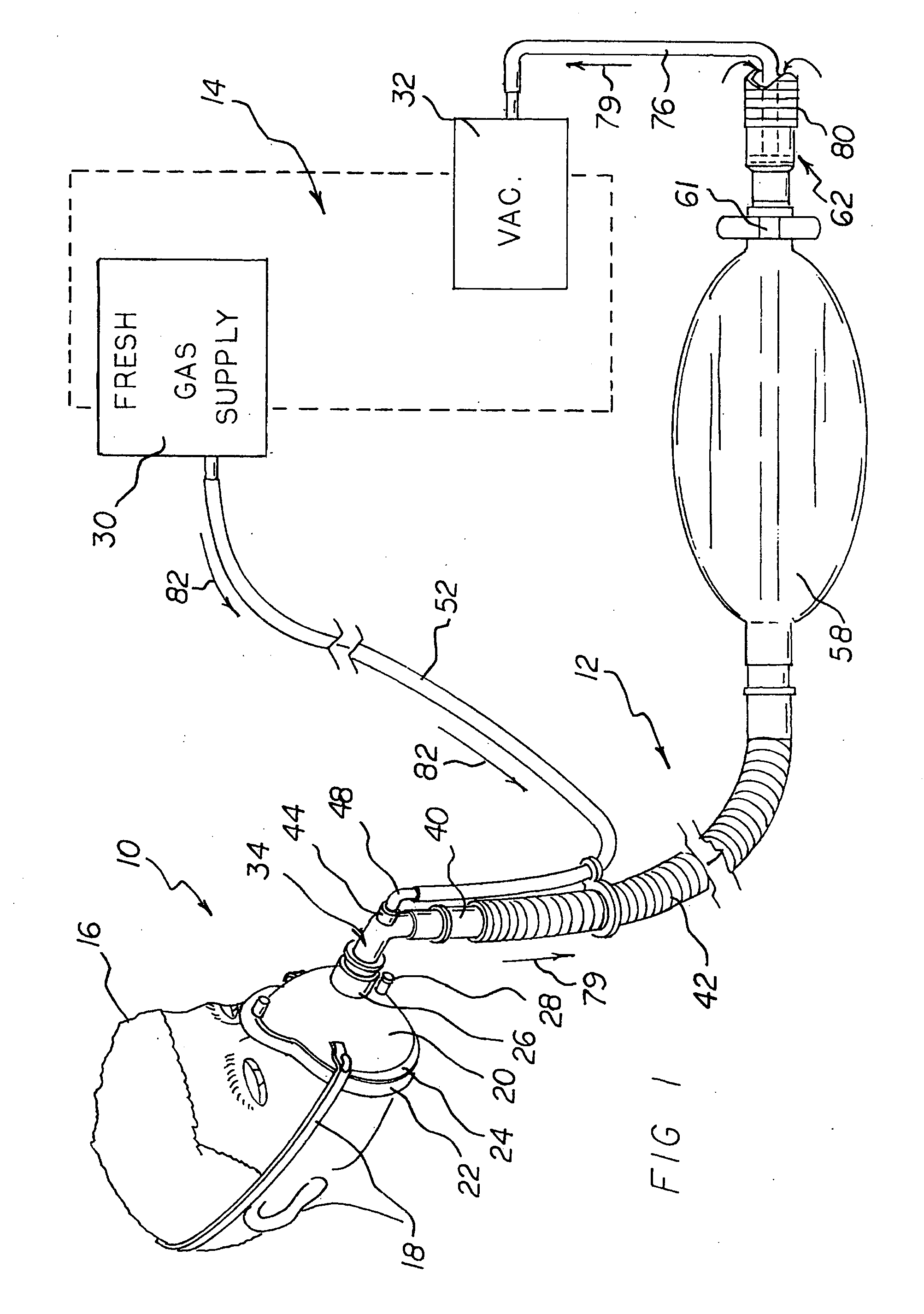
[0029]With reference now to FIGS. 1-4 of the Drawings, there is shown a preferred embodiment of the new and improved respiratory face mask and breathing circuit assembly of the present invention generally comprising a face mask 10, a breathing circuit 12, and a gas supply and scavenging device 14.

[0030]As schematically depicted in FIG. 1, face mask 10 is fitted on the face of a patient 16 via a headstrap 18 (preferably elastic) removably attachable to the face mask via anchors or the like on the opposed edges thereof. The headstrap helps to stabilize the mask on the face and head of a person, preferably before, during and / or after surgery. Many of the details of construction of the face mask 10 and headstrap 18 are outside the scope of the present invention. For a more detailed understanding of same, the interested reader is directed to my prior applications (incorporated herein by reference). Suffice it to say for purposes of fully understanding the present invention, face mask 10 ...


PUM


Abstract

A respiratory face mask is provided suitably sized and configured to engage at least the nose portion and mouth portion of a patient's face. Gas from a gas supply and scavenging set normally used in dentistry is operatively coupled to the mask via a breathing circuit to supply fresh gas and evacuate exhaled waste gas. A gas flow compensator in the breathing circuit automatically prevents re-breathing of exhaled gas. Because the mask has a sealing cushion, contamination of the clinical room where the apparatus is being used also is avoided.

Description

RELATED APPLICATIONS[0001]The present application is a continuation-in-part (CIP) of my prior copending U.S. patent application Ser. No. 12 / 221,379; filed Aug. 8, 2008, which in turn is a continuation-in-part (CIP) of my copending prior application Ser. No. 11 / 809,435; filed Jun. 1, 2007 (herein “prior applications”). The aforesaid prior applications hereby are incorporated herein and made part hereof by this reference.BACKGROUND OF THE INVENTION[0002]1. Field of the Invention[0003]The present application relates generally to devices for delivering respiratory gas or gases in medical applications, and more particularly, to a new and improved respiratory face mask and breathing circuit assembly that is especially useful in administering gases, such as anesthesia inhalation agents, or oxygen, or air, or mixtures of same, for medical purposes, and as such represents an improvement over the similar device or devices disclosed in my prior applications.[0004]2. Description of the Prior Ar...

Claims


Application Information

Patent Timeline
IPC IPC(8): A61M16/06A61M16/12
CPCA61M16/0078A61M16/009A61M16/06A61M16/0683A61M16/0816A61M16/085A61M2202/0208A61M2202/0283A61M2230/432A61M16/0833A61M16/104
Inventor NASHED, RAMSES
Owner NASHED RAMSES
Why Eureka
Try Eureka