Silent discharge plasma apparatus

Active Publication Date: 2009-09-24
MITSUBISHI ELECTRIC CORP
View PDF3 Cites 28 Cited by
  • Summary
  • Abstract
  • Description
  • Claims
  • Application Information

AI Technical Summary

Benefits of technology

[0011]In the case of the silent discharge plasma apparatus according to the present invention, the conductive thin film electrode instantly senses a short-circuit current upon destruction of a glass tube and selectively eliminates its conductive thin film so that supply of power is stopped. This plasma apparatus is thus capable of conti

Problems solved by technology

However, in the event that abnormal discharge developing between the metal substrates increases a temperature or leads to application of an excessively high voltage, the voltage resistance characteristic of a dielectric member may get impaired, which could give rise to

Method used


Image

  • Silent discharge plasma apparatus
  • Silent discharge plasma apparatus
  • Silent discharge plasma apparatus

Examples


Example

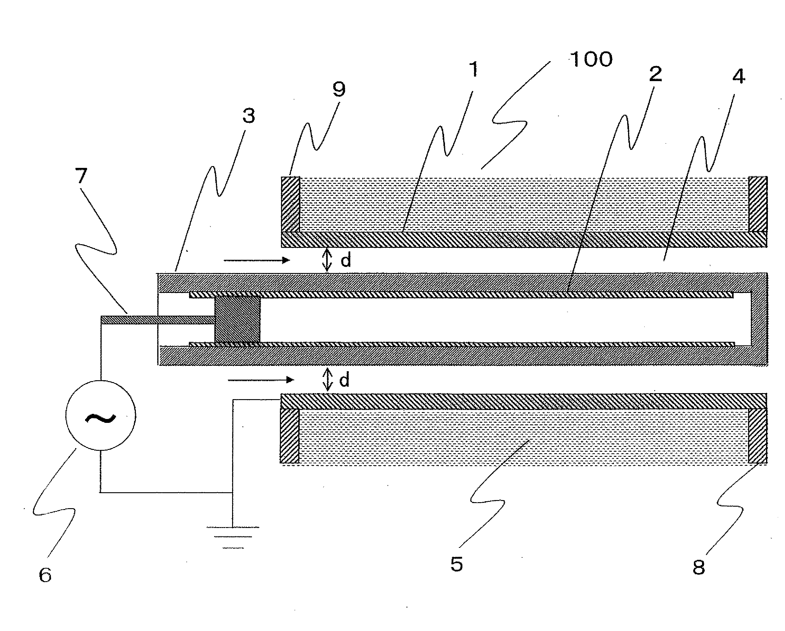
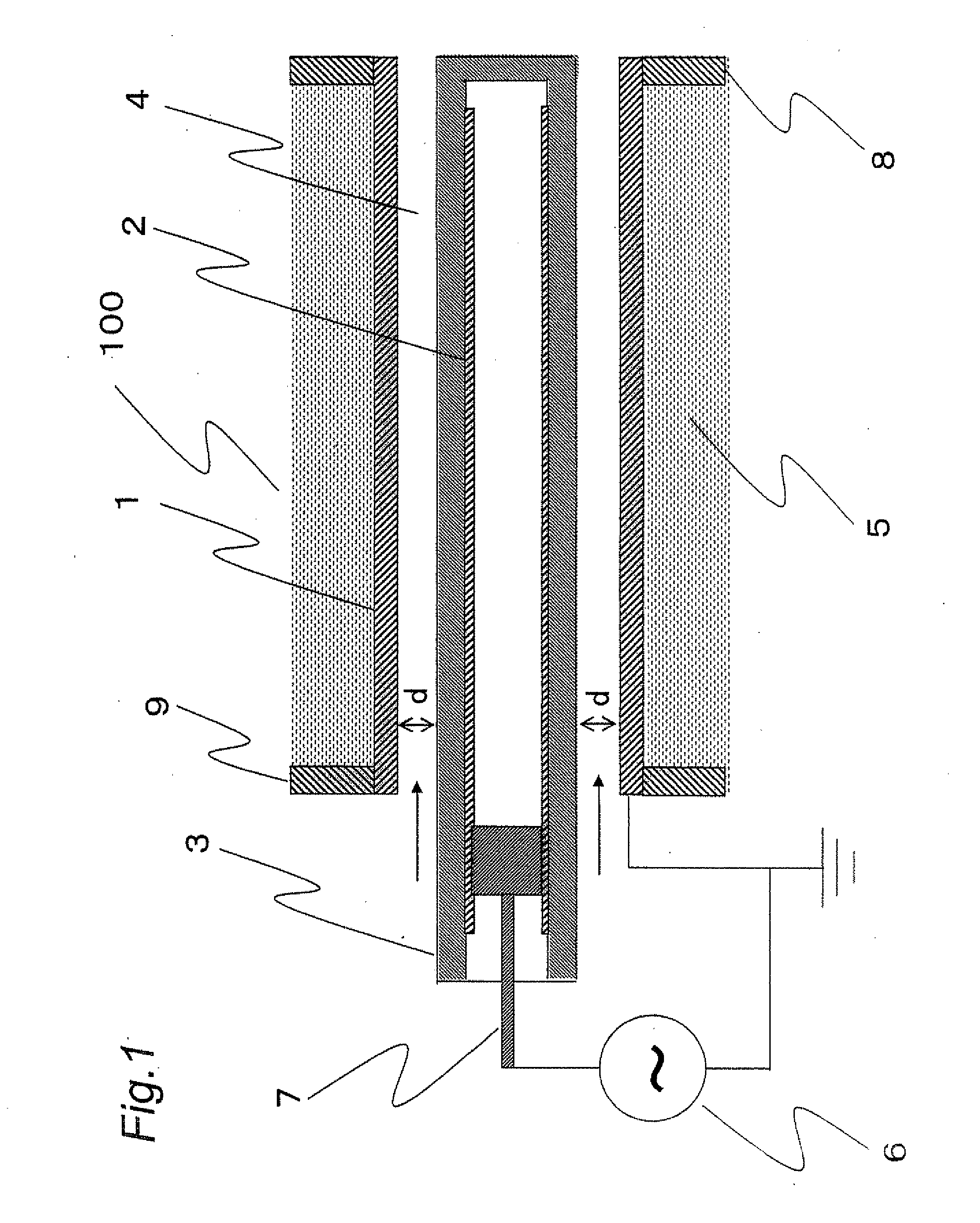
[0038]FIG. 1 is a cross sectional view of an ozone generator according to the first embodiment. In FIG. 1, the ozone generator 100 includes a ground electrode 1 and a high voltage electrode 2 which are opposed against each other over a predetermined airspace length d. The ground electrode 1 and the high voltage electrode 2 are both coaxial cylindrical electrodes, and there is at least one dielectric member 3 between the ground electrode 1 and the high voltage electrode 2. The airspace length d will be referred to as a “discharge airspace length” and the spaced defined by the discharge airspace length will be referred to as a “discharge space 4”.

[0039]One or both of the ground electrode 1 and the high voltage electrode 2 internally includes cooling water paths 5 for carrying tap water or pure water, to thereby cool down the discharge space 4.

[0040]A gas containing oxygen is introduced as a raw material gas to the discharge space 4, and as an alternating-current high voltage is applie...

Example

Second Embodiment

[0106]According to the first embodiment, upon glass tube destruction, the high voltage electrode around the destroyed section eliminates itself as it exfoliates, evaporates or gets sublimated, thereby realizing an operation of protecting against short circuit without using high voltage fuses. It was confirmed that in the instance as that shown in FIG. 13 as well, that is, when the high voltage electrode around a destroyed section 18 got oxidized instead of eliminated, a similar operation of protecting against short circuit to that according to the first embodiment was realized.

[0107]FIG. 13 is a partial cross sectional view of an ozone generator according to the second embodiment. The sections denoted at the same reference symbols as those appearing in FIG. 1 are the same or corresponding sections. The high voltage electrode 2 is a conductive thin film which is formed in a similar manner to that according to the first embodiment, and in the illustrate condition, the...

Example

Third Embodiment

[0111]In the case of an ozone generator whose capacity is small or medium, i.e., an ozone generator which generates ozone in the amount of about 10 kg / h or less, upon glass tube destruction, the area in which a high voltage electrode eliminates itself is extremely narrow as described in relation to the first embodiment.

[0112]However, in the event that a conductive thin film as that according to the first embodiment is disposed as high voltage electrodes in a large-capacity ozone generator which generates ozone in the amount of about 40 kg / h for instance, upon glass tube destruction, as shown in FIG. 14, a high voltage electrode in its entirety from the position at which the power feeding member 7 contacts the high voltage electrode 2 to an initially eliminated section 20 having the shape of a through hole of the glass tube 3 may get eliminated due to the thermal influence exerted by arc discharge (self-eliminated section 21).

[0113]Further, when a short-circuit curren...


PUM

PropertyMeasurementUnit
Timeaaaaaaaaaa
Thicknessaaaaaaaaaa
Diameteraaaaaaaaaa

Abstract

A silent discharge plasma apparatus includes a dielectric member, a pair of electrodes opposed to each other across the dielectric member and an alternating-current source applying an alternating-current voltage between the electrodes and causing a discharge. A gas is supplied to a discharge space, where discharge occurs, and a plasma is produced. At least one of the electrodes includes a conductive power feeding thin film on the dielectric member. When the dielectric member is destroyed and an arc discharge develops between the electrodes, the power feeding thin film is eliminated or oxidized, and the arc discharge is stopped.

Description

TECHNICAL FIELD[0001]The present invention relates to a silent discharge plasma apparatus, and more particularly, to a silent discharge plasma apparatus equipped with a conductive thin film electrode which permits a non-destroyed section alone to continue a safe operation.BACKGROUND ART[0002]One example of a conventional silent discharge plasma apparatus is a silent discharge ozone generator. A silent discharge ozone generator generally uses an electrode structure which uses a glass tube as a dielectric barrier. The presence of a dielectric barrier between metal substrates prevents a transition of discharge developing between the metal substrates to arc so that discharge repeatedly stops and develops.[0003]However, in the event that abnormal discharge developing between the metal substrates increases a temperature or leads to application of an excessively high voltage, the voltage resistance characteristic of a dielectric member may get impaired, which could give rise to dielectric ...

Claims


Application Information

Patent Timeline
IPC IPC(8): C23C16/00B01J19/08B44C1/22C23F1/00
CPCC01B13/11C01B2201/12C01B2201/14C01B2201/22C01B2201/24C01B2201/32H05H1/24C01B2201/60C01B2201/64C01B2201/76C01B2201/90H01T19/00C01B2201/34H05H1/2406H05H1/2437
Inventor WADA, NOBORUKUZUMOTO, MASAKINAKATANI, HAJIMEIGEHARA, HIROYUKIESAKI, NORIMITSUMINE, SHINGOTAMIDA, TAICHIRO
Owner MITSUBISHI ELECTRIC CORP
Why Eureka
Try Eureka