Micromechanical device and method of manufacturing micromechanical device

a micromechanical device and micromechanical technology, applied in the direction of electrical apparatus casings/cabinets/drawers, relays, hermetically sealed casings, etc., can solve the problems of difficult to settle the vibration of the micromachine, the vibration occurring when the electrostatic force is removed, etc., and achieve the effect of higher viscosity coefficien

Active Publication Date: 2009-09-24
KK TOSHIBA
View PDF3 Cites 53 Cited by
  • Summary
  • Abstract
  • Description
  • Claims
  • Application Information

AI Technical Summary

Benefits of technology

[0011]An example of the present invention is a micromechanical device comprising, a substrate in which a signal line is provided on a principal surface, a micromachine which is mounted on the principal surface of the substrate, is formed of a conductive material into a beam-like shape, is elastically deformed by a function of an electric field in such a manner that the beam-like part moves closer to or apart from the signal line, and changes the electric characteristics concomitantl

Problems solved by technology

However, in the technique described above, there has been the following problem.
That is, in the MEMS element as a beam-like micromachine, the vibration occurring when the electrostatic force is removed is hard to be settled because of the sprin

Method used


Image

  • Micromechanical device and method of manufacturing micromechanical device
  • Micromechanical device and method of manufacturing micromechanical device
  • Micromechanical device and method of manufacturing micromechanical device

Examples


Embodiment Construction

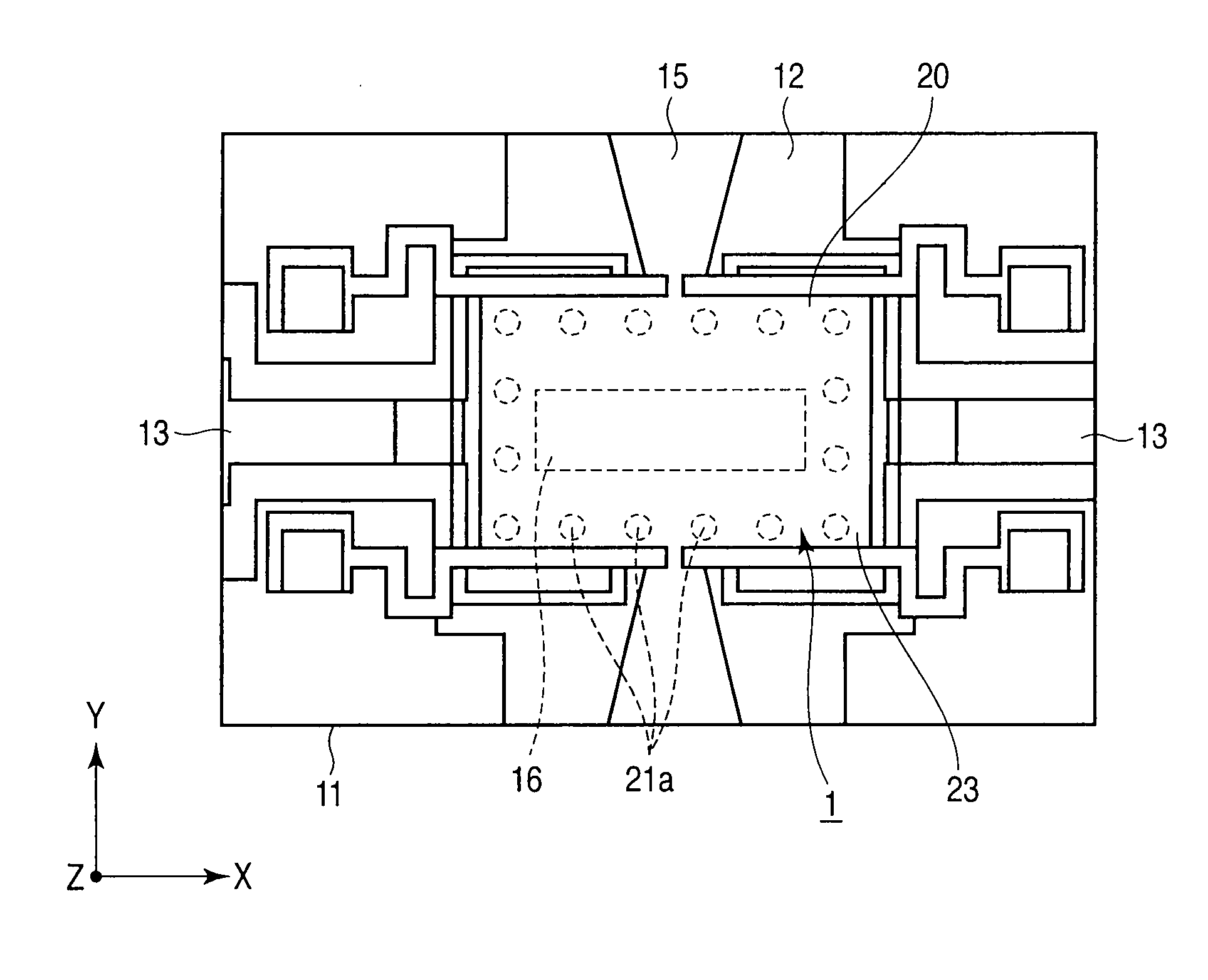
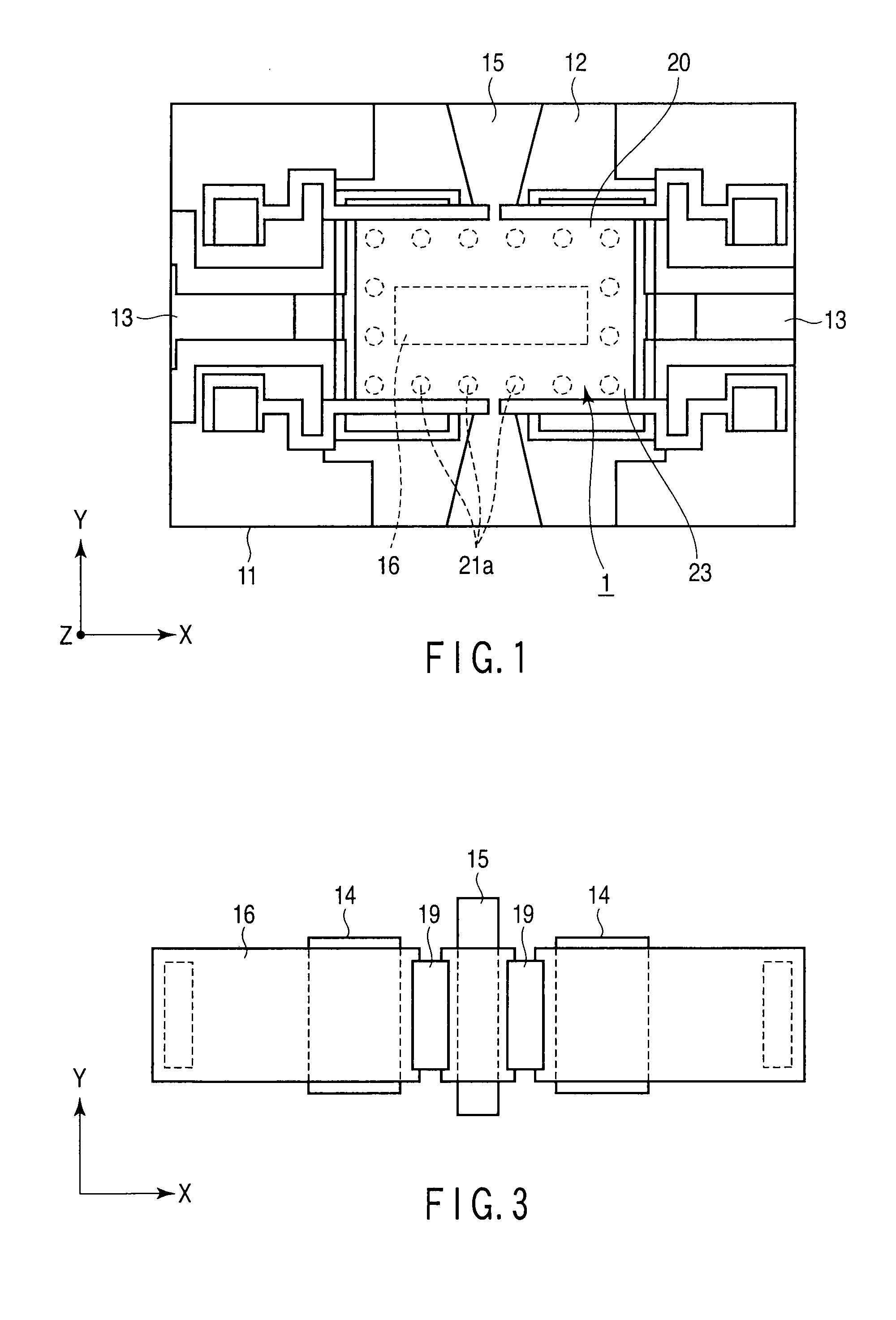
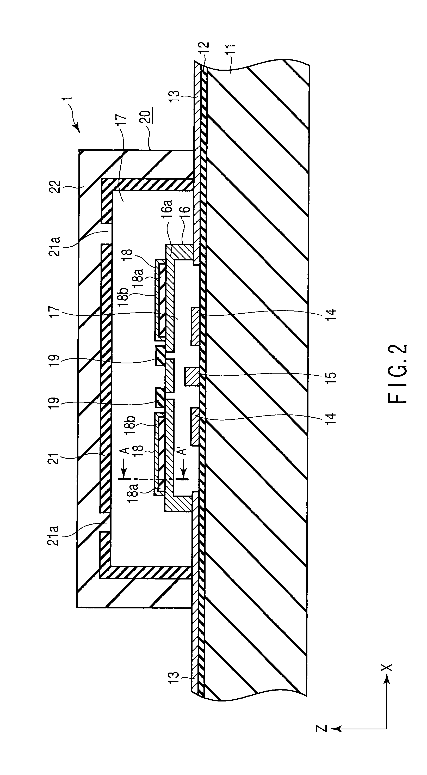
[0036]A micromechanical device 1 according to a first embodiment of the present invention will be described below with reference to FIGS. 1 to 3. It should be noted that in each drawing, the configuration is schematically shown by appropriately enlarging, reducing, and omitting the configuration. In FIGS. 1 to 3, X, Y, and Z each indicate three directions perpendicular to each other.

[0037]The micromechanical device 1 is, for example, Micro-Electro-Mechanical-Systems (MEMS), and includes a base substrate 11 constituting a substrate, an insulating layer 12, signal wiring 15 (signal line), a MEMS element 16 (micromachine), deformation restraint sections 18, and the like. Further, the MEMS element 16 is sealed airtight by a combination of a sealing body 20 with the substrate. An atmosphere of a gas of normal pressure is sealed in a hollow section 17 which is formed in the sealing body 20. The sealing body 20 is constituted by stacking a first sealing body 21 defining the hollow section ...


PUM

PropertyMeasurementUnit
Deformation enthalpyaaaaaaaaaa

Abstract

An example of the present invention is a micromechanical device including, a substrate in which a signal line is provided, a micromachine which is mounted on the substrate, is formed of a conductive material into a beam-like shape, is elastically deformed by a function of an electric field in such a manner that the beam-like part moves closer to or apart from the signal line, and changes the electric characteristics concomitantly with the deformation, a deformation restraint section constituted of a material having a higher viscosity coefficient than the conductive material, provided on the opposite side of the micromachine to the signal line, for restraining deformation of the micromachine in a direction in which the micromachine is separated from the signal line, and a sealing body provided on the principal surface of the substrate, for covering the micromachine with a hollow section located therebetween.

Description

CROSS-REFERENCE TO RELATED APPLICATIONS[0001]This application is based upon and claims the benefit of priority from prior Japanese Patent Application No. 2008-071571, filed Mar. 19, 2008, the entire contents of which are incorporated herein by reference.BACKGROUND OF THE INVENTION[0002]1. Field of the Invention[0003]The present invention relates to a micromechanical device such as packaging of a micro-electro-mechanical-systems, and a method of manufacturing the micromechanical device.[0004]2. Description of the Related Art[0005]As an example of the micromechanical device, Micro-Electro-Mechanical-Systems (MEMS) 101 in which a MEMS element 104 as a micromachine having a motion is mounted on a substrate 102, and is sealed in a hollow state as shown in FIGS. 19 to 21 are known. Such an example is shown in, for example, Jpn. Pat. Appln. KOKAI Publication No. 2005-207959 or U.S. Pat. No. 7,008,812B1.[0006]The MEMS 101 is constituted of a substrate 102, an insulating layer 103, a MEMS el...

Claims


Application Information

Patent Timeline
IPC IPC(8): H05K5/06H05K7/02
CPCB81B3/0078B81B2201/016B81B2203/0109Y10T29/49002H01H3/60H01H59/0009H01H1/50
Inventor OBATA, SUSUMUINOUE, MICHINOBUMIYAGI, TAKESHI
Owner KK TOSHIBA
Why Eureka
Try Eureka