Anodizing method and apparatus

an anodizing method and anodizing technology, applied in the direction of electrolysis components, vacuum evaporation coatings, coatings, etc., can solve the problems of increasing and affecting the treatment quality, so as to improve the treatment speed and treatment quality, increase the treatment speed, and reduce the load on the power supply unit

Inactive Publication Date: 2009-09-24
SUZUKI MOTOR CORP
View PDF6 Cites 13 Cited by
  • Summary
  • Abstract
  • Description
  • Claims
  • Application Information

AI Technical Summary

Benefits of technology

[0031]In the present invention, since the above-described anodizing method is employed, the positive voltage application time and pulse frequency that are most suitable for the workpiece can be set qualitatively without depending on the shape of the workpiece and number of workpieces to be treated, and the treatment speed and treatment quality can be improved. Also, in the range of voltage and frequency allowed by the power supply unit, an optimum and necessary minimum voltage and frequency according to the treatment surface area can be determined while the treatment speed and treatment quality are maintained. Therefore, the load on the power supply unit can be reduced.
[0032]In the present invention, if the normal positive voltage application time is determined in the range of 0.6 to 3 times the peak arrival time, and a supplied voltage is increased in the range in which the average current value at the determined normal positive voltage application time does not exceed the average current value at the positive voltage application time that is two times the peak arrival time, the anodizing method is advantageous in increasing the treatment speed while the treatment quality is maintained and in obtaining a thick film.
[0033]In the present invention, if the step is performed in which the slow-up treatment for increasing a positive voltage from the positive voltage at the time of treatment start, which is lower than a set positive voltage, to the set positive voltage continuously or stepwise is performed before the anodizing treatment using the set positive voltage, and the normal positive voltage application time is determined during the slow-up treatment, immediately after the slow-up period has elapsed, the process can shift to the anodizing treatment using the normal positive voltage application time, so that the treatment time can be shortened as a whole.

Problems solved by technology

However, in the actual treatment process, in a case in which many parts are treated at the same time or in a case in which large parts are treated, to secure the film growth rate, a high voltage proportional to the increase in treatment surface area must be applied, and therefore the load on a power supply unit increases.
Even if the voltage and frequency are increased unreasonably, the load on the power supply unit increases, and also the treatment quality may be rather degraded.
However, even if a tentative treatment condition can be determined experimentally in a limited treatment environment, there has been no evaluation reference and method capable of determining the optimum treatment condition qualitatively without depending on the shape of workpiece and number of workpieces to be treated.

Method used


Image

  • Anodizing method and apparatus
  • Anodizing method and apparatus
  • Anodizing method and apparatus

Examples


Embodiment Construction

[0046]An embodiment of the present invention will now be described in detail with reference to the accompanying drawings.

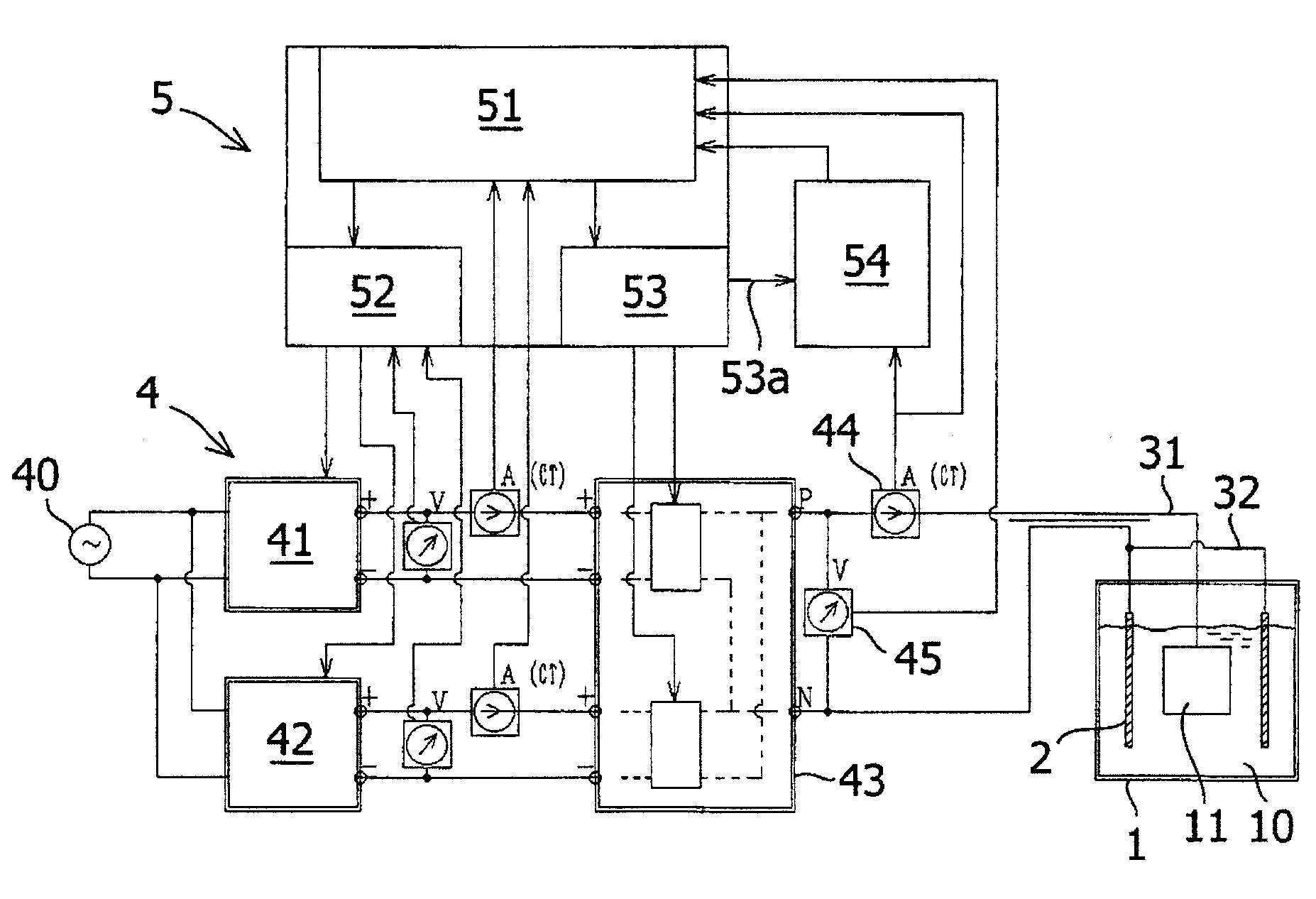
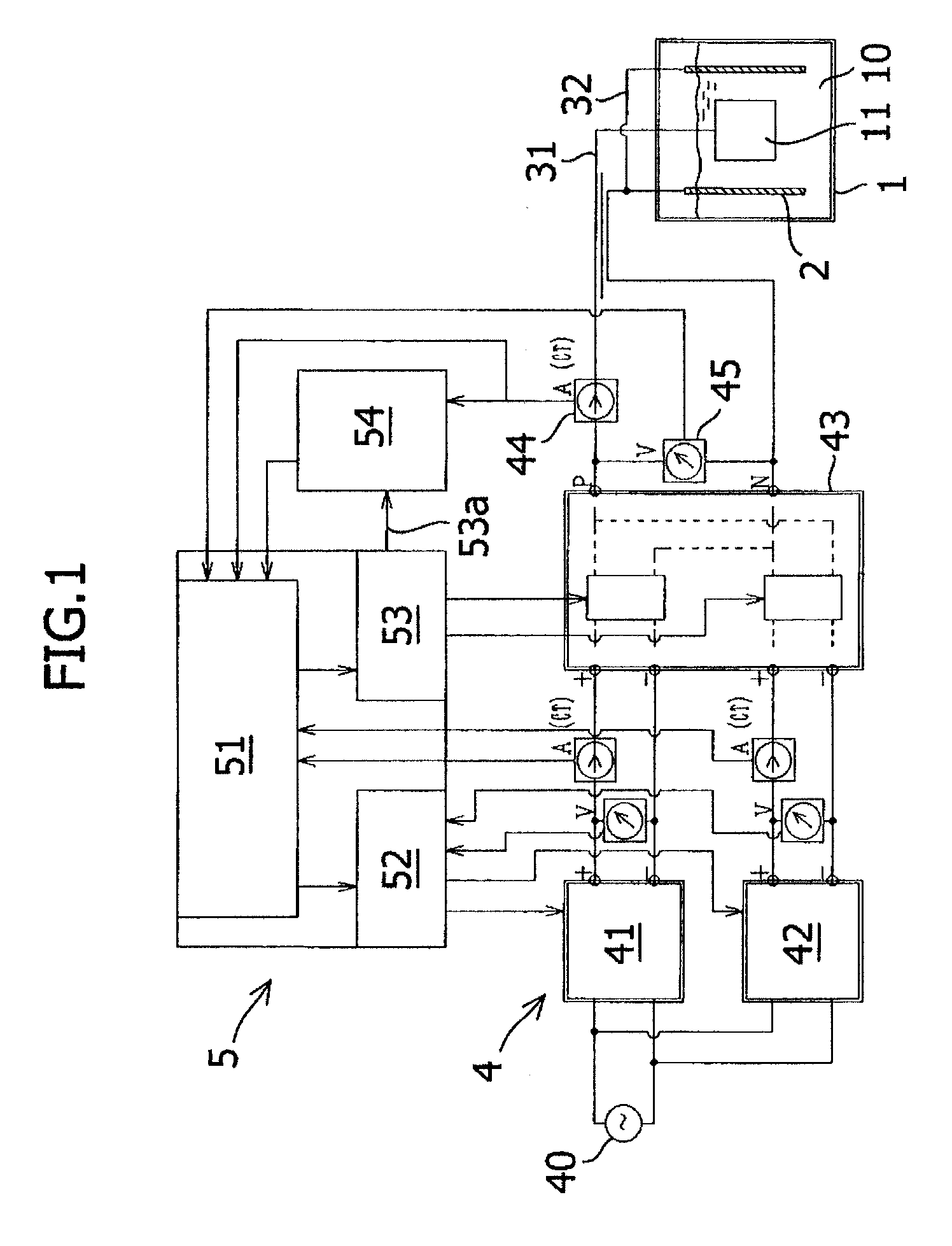
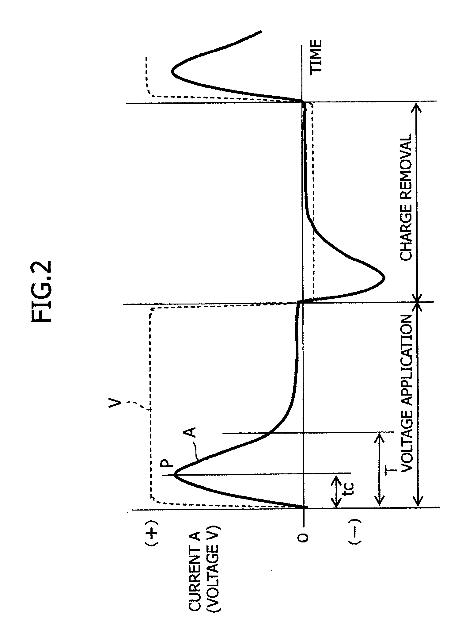
[0047]FIG. 1 is a configuration diagram of an anodizing apparatus in accordance with the embodiment of the present invention. In FIG. 1, the anodizing apparatus is mainly made up of a treatment tank 1 for storing an electrolytic solution 10, a cathode plate 2 disposed in the treatment tank 1, a support for supporting a workpiece 11 made of aluminum or aluminum alloy at a position at which the workpiece 11 is immersed in the electrolytic solution 10, a power supply unit 4 for performing treatment in which the application of positive voltage for a very short period of time and the removal of charges are repeated alternately by applying a very short-period bipolar pulse voltage to between the workpiece 11 and the cathode plate 2, and a control unit 5.

[0048]The power supply unit 4 includes a DC power supply 41 for positive voltage and a DC power supply 42 for negative...


PUM

PropertyMeasurementUnit
peak arrival timeaaaaaaaaaa
supplied voltageaaaaaaaaaa

Abstract

An anodizing method in which a workpiece made of aluminum or aluminum alloy is immersed in an electrolytic solution, and treatment is performed in which the application of positive voltage for a very short period of time and the removal of charges are repeated alternately between the workpiece and a cathode arranged in the electrolytic solution includes a step of performing treatment in which the positive voltage application and the charge removal are repeated in a tentative cycle, measuring the control point arrival time of a current waveform at the positive voltage application period, and determining normal positive voltage application time based on the control point arrival time; and a step of performing treatment in which the application of positive voltage and the removal of charges are repeated in a cycle corresponding to the normal positive voltage application time, and forming an anodized film on the surface of the workpiece.

Description

CROSS-REFERENCE TO RELATED APPLICATIONS[0001]The present application claims priority from Japanese Application No. 2008-075683, filed Mar. 24, 2008, the disclosure of which is incorporated herein by reference.FIELD OF THE INVENTION[0002]The present invention relates to a method for anodizing a workpiece made of aluminum or aluminum alloy and to an apparatus for carrying out the method.BACKGROUND OF THE INVENTION[0003]Conventionally, members made of aluminum or aluminum alloy, such as a variety of exterior parts and structural parts including pistons and cylinders of internal combustion engines and hydraulic-pneumatic pistons and cylinders, have been anodized to form an anodized film (alumite) on the surfaces of the members for the purpose of improving corrosion resistance and wear resistance or coloring.[0004]For this anodizing treatment, DC anodizing treatment, in which electrolyzing treatment is performed by applying DC voltage between a workpiece (anode) and a cathode in the stat...

Claims


Application Information

Patent Timeline
Patent Type & Authority Applications(United States)
IPC IPC(8): C25D21/12C25D19/00
CPCC25D11/04C25D11/005C25D11/024C25D21/12
Inventor YAMAMOTO, TOMOHARUTANAKA, HIROOMIFUJITA, MASAHIRO
Owner SUZUKI MOTOR CORP
Why Eureka
Try Eureka