Method for manufacturing perpendicular magnetic recording head

a technology of perpendicular magnetic and recording head, which is applied in the direction of record information storage, instruments, vacuum evaporation coating, etc., can solve the problems of non-uniform distribution, method of controlling the variation in width, and metal oxide may be non-uniformly removed from the surface of the underlying metal wiring layer, etc., to achieve more progress and uniform track width

Inactive Publication Date: 2009-09-24
WESTERN DIGITAL TECH INC
View PDF7 Cites 6 Cited by
  • Summary
  • Abstract
  • Description
  • Claims
  • Application Information

AI Technical Summary

Benefits of technology

[0007]In reactive ion etching (RIE) performed during formation of a main magnetic pole of a perpendicular magnetic recording head, etching at an outer peripheral portion of a wafer progresses more easily than etching at a central portion of the wafer. The width of a mask pattern on the central portion of the wafer is large, while the width of the mask pattern on the outer peripheral portion of the wafer is small. When ion milling is performed in this state, the width of the main magnetic pole located at the central portion of the wafer is large, while the width of the main magnetic pole located at the outer peripheral portion of the wafer is small.
[0008]Embodiments of the present invention help to provide a method for manufacturing a perpendicular magnetic recording head including a main magnetic pole having a width that does not generally vary. According to the embodiment of FIG. 2, a magnetic film 440, a first inorganic mask film 442, an organic film 444, a second inorganic mask film 446, and a resist pattern 448 are formed in this order. Reactive ion etching (RIE) is performed using the resist pattern 448 as a mask to etch the second inorganic mask film 446 and the organic film 444 and form a mask for the subsequent step. A flow rate of an Ar gas is then controlled, and ion milling 1 is performed, to correct a difference between the width of the mask located at the central portion of the wafer and the width of the mask located at the outer peripheral portion of the wafer. The magnetic film 440 is processed to have a uniform track width. Ion milling 2 is then performed to form the main magnetic pole 44 having an inverted trapezoidal shape.

Problems solved by technology

That is, in a process for forming a multi-layer wiring using an organic film as an interlayer insulating film, when Ar ion milling is performed in order to remove a metal oxide from the surface of an underlying metal wiring layer, a non-uniform distribution tends to occur on the surface of a wafer forming a multi-layer wiring substrate, and the Ar ion milling tends to be performed on a central portion of the wafer at high speed and on an outer peripheral portion of the wafer at low speed.
Thus, the metal oxide may be non-uniformly removed from the surface of the underlying metal wiring layer present on the wafer.
Furthermore, Patent Documents 2 and 3 do not describe a method for controlling the variation in the width of the main magnetic pole.

Method used


Image

  • Method for manufacturing perpendicular magnetic recording head
  • Method for manufacturing perpendicular magnetic recording head
  • Method for manufacturing perpendicular magnetic recording head

Examples


Embodiment Construction

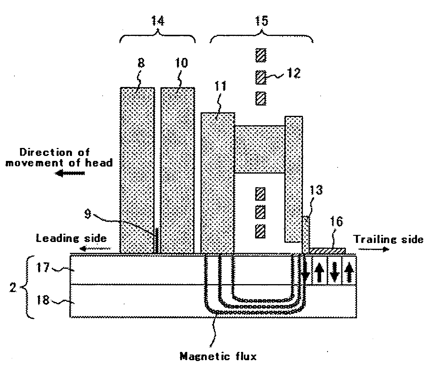
[0025]Embodiments of the present invention relate to a method for manufacturing a perpendicular magnetic recording head mounted in a magnetic recording / reproducing device, and more particularly to a method for manufacturing a perpendicular magnetic recording head including a main magnetic pole having a width that does not generally vary.

[0026]An object of embodiments of the present invention is to provide a method for manufacturing a perpendicular magnetic recording head including a main magnetic pole having a width that does not generally vary.

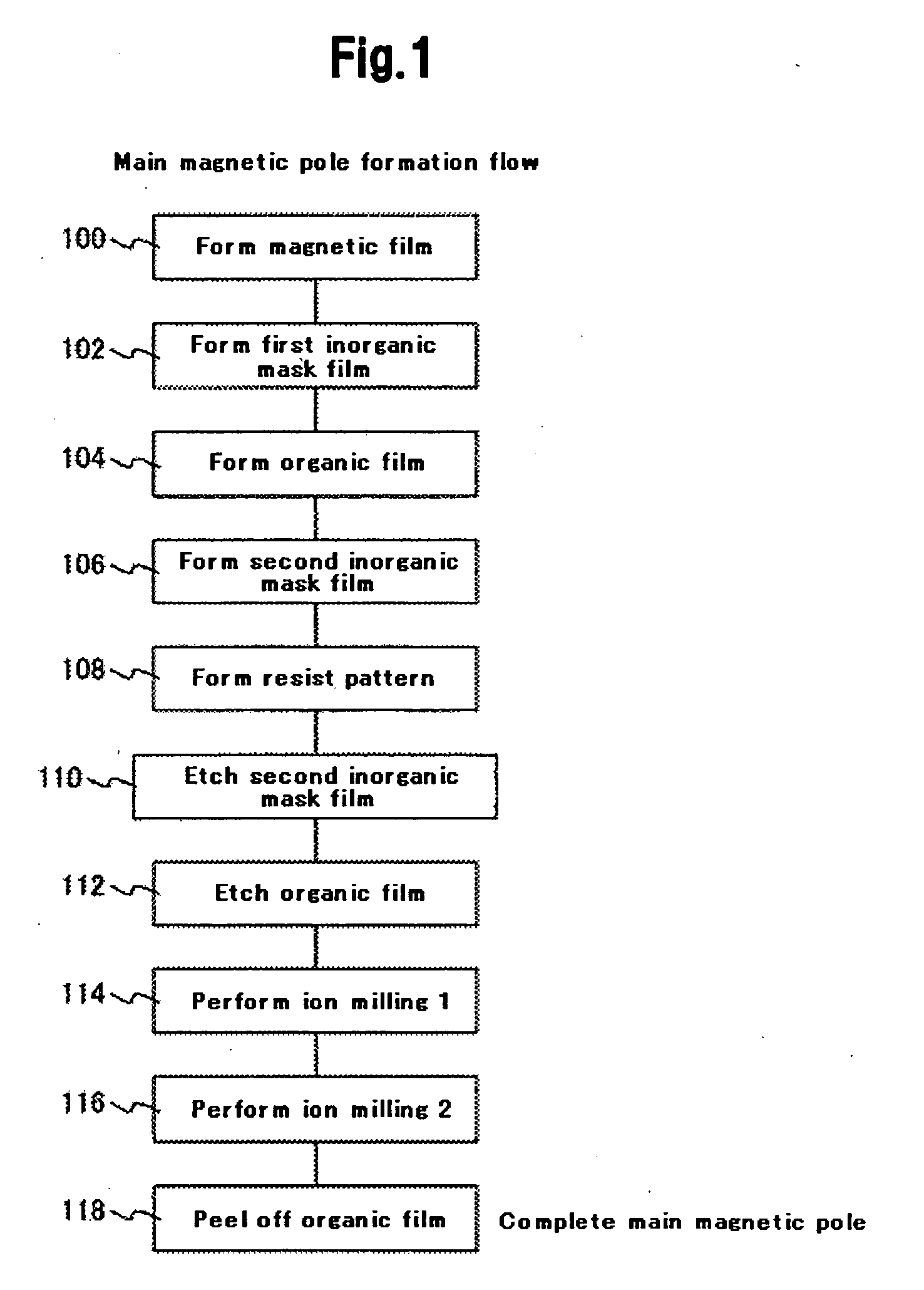
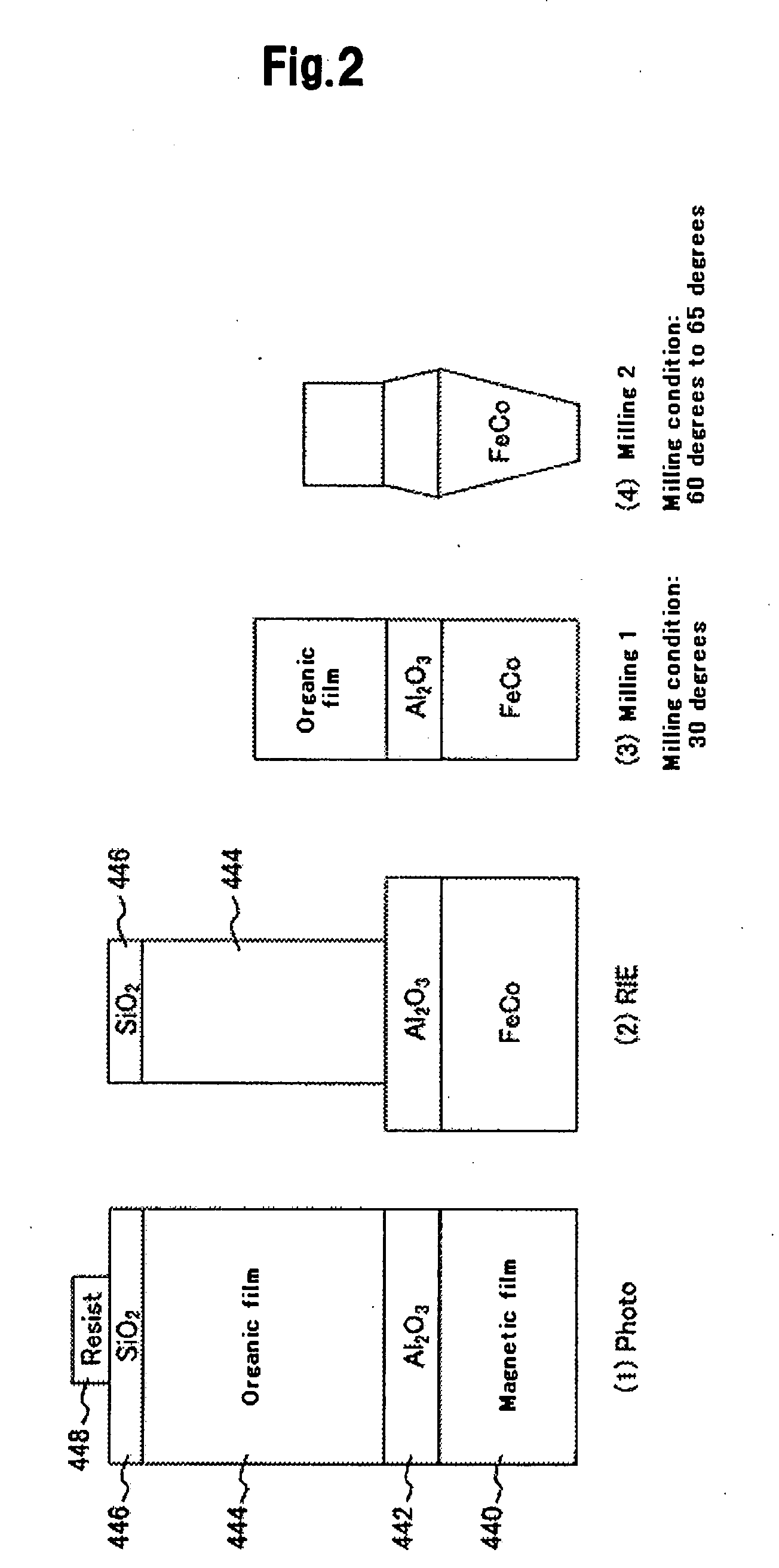
[0027]A typical method for manufacturing a perpendicular magnetic recording head according to an embodiment of the present invention comprises the steps of: forming a main magnetic pole; forming an auxiliary magnetic pole; and forming a coil, wherein the step of forming the main magnetic pole includes the sub-steps of: forming a magnetic film above a wafer; forming a mask member on the magnetic film; performing reactive ion etching (RIE) on t...


PUM

PropertyMeasurementUnit
bias poweraaaaaaaaaa
pressureaaaaaaaaaa
pressureaaaaaaaaaa

Abstract

Embodiments of the present invention help to provide a method for manufacturing a perpendicular magnetic recording head including a main magnetic pole having a width that does not generally vary. According to one embodiment, a magnetic film, a first inorganic mask film, an organic film, a second inorganic mask film, and a resist pattern are formed in this order. Reactive ion etching (RIE) is performed using the resist pattern as a mask to etch the second inorganic mask film and the organic film and form a mask for the subsequent step. A flow rate of an Ar gas is then controlled, and ion milling is performed, to correct a difference between the width of the mask located at the central portion of the wafer and the width of the mask located at the outer peripheral portion of the wafer. The magnetic film is processed to have a uniform track width. Ion milling is then performed to form the main magnetic pole having an inverted trapezoidal shape.

Description

CROSS-REFERENCE TO RELATED APPLICATION[0001]The instant nonprovisional patent application claims priority to Japanese Patent Application No. 2008-075799 filed Mar. 24, 2008, and which is incorporated by reference in its entirety herein for all purposes.BACKGROUND OF THE INVENTION[0002]With the recent development of the information society, it has been sought to increase an integration density and operation speed of a magnetic recording / reproducing device representing a magnetic disk device, and to reduce the size of the magnetic recording / reproducing device on the market. As perpendicular magnetic recording scheme can meet these needs. The perpendicular magnetic recording scheme is suitable for an increase in a surface recording density in principle. In the perpendicular magnetic recording scheme, the higher a linear recording density of a pattern recorded on a magnetic disk, the smaller the intensity of a diamagnetic field and the more the intensity of magnetization is stabilized. ...

Claims


Application Information

Patent Timeline
Patent Type & Authority Applications(United States)
IPC IPC(8): B44C1/22
CPCG11B5/1278G11B5/3163G11B5/3116
Inventor OKADA, TOMOHIROKIMURA, HISASHISHINTANI, TAKUUMEZAWA, TADASHI
Owner WESTERN DIGITAL TECH INC
Why Eureka
Try Eureka