Spectrally Tunable Infrared Image Sensor Having Multi-Band Stacked Detectors

Active Publication Date: 2009-09-24
DRS NETWORK & IMAGING SYST
View PDF4 Cites 39 Cited by
  • Summary
  • Abstract
  • Description
  • Claims
  • Application Information

AI Technical Summary

Benefits of technology

[0006]Systems and articles of manufacture consistent with the present invention provide a tunable infrared detector and an infrared imaging system employing one or more of the tunable infrared detectors. The tunable infrared detector comprises a substrate, a bottom wavelength detector formed over the substrate, a top wavelength detector formed over the first wavelength detector layer, and an interferometer filter formed over the top wavelength detector layer and the bottom wavelength detector layer. The interferometer filter is operatively configured to pass a first wavelength

Problems solved by technology

In practice, the range is often lower due to the limitations in spectral width of the reflectors used to form the F-P resonant cavity.
It is therefore not possible to use a si

Method used


Image

  • Spectrally Tunable Infrared Image Sensor Having Multi-Band Stacked Detectors
  • Spectrally Tunable Infrared Image Sensor Having Multi-Band Stacked Detectors
  • Spectrally Tunable Infrared Image Sensor Having Multi-Band Stacked Detectors

Examples


Embodiment Construction

[0014]Reference will now be made in detail to an implementation in accordance with methods, systems, and products consistent with the present invention as illustrated in the accompanying drawings.

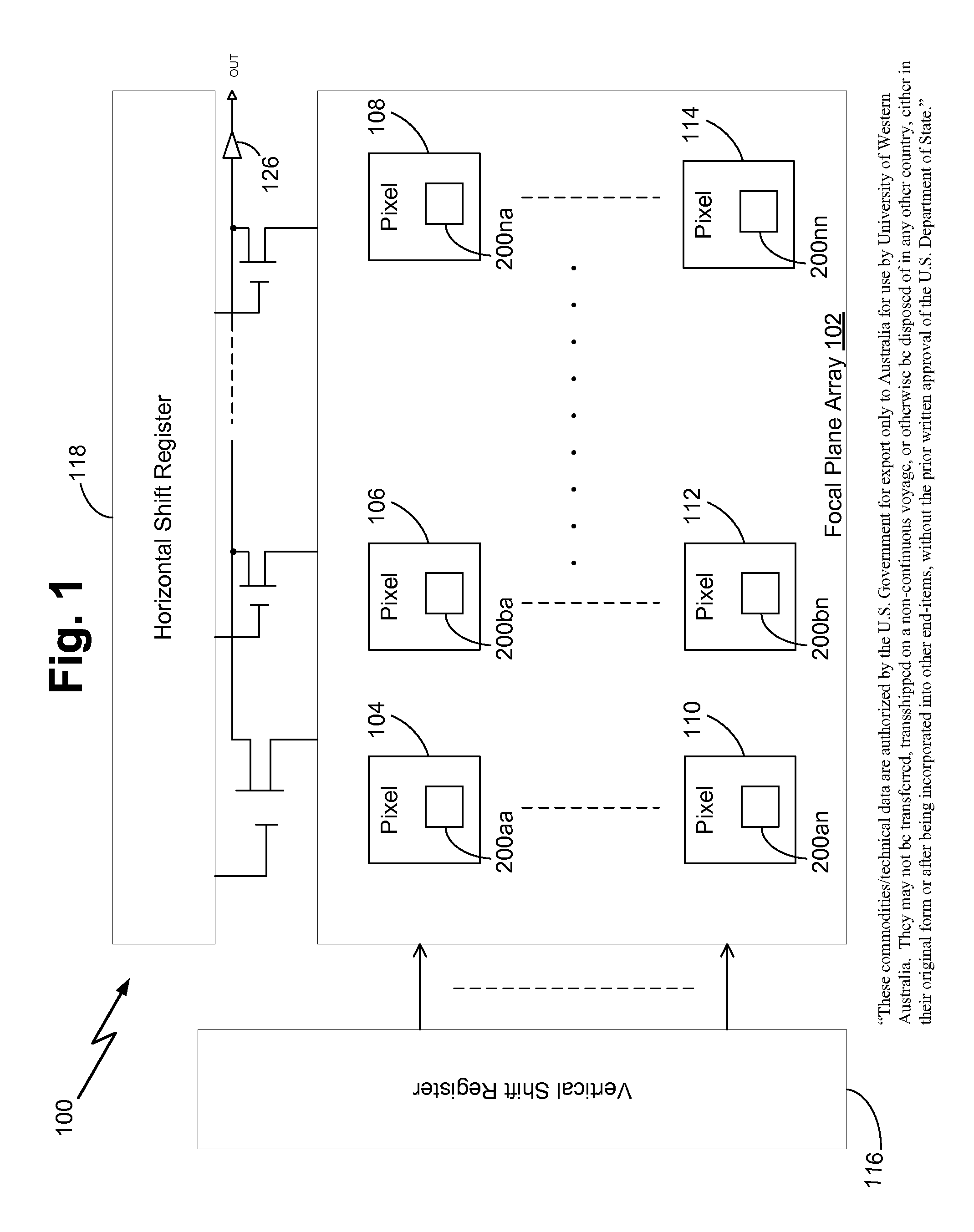
[0015]FIG. 1 is a block diagram of an exemplary infrared imaging system 100 having a focal plane array 102. The focal plane array includes a plurality of pixels 104, 106, 108, 110, 112 and 114 each of which includes a tunable infrared detector 200aa-200nn consistent with the present invention. In the implementation shown in FIG. 1, the infrared imaging system 100 also includes a vertical shift register 116 operatively configured to select a row of pixels (e.g., pixels 104, 106, and 108) and a horizontal shift register 118 operatively configured to shift the selected row of pixels to an amplifier 126 for output to an image processor (not shown in figures).

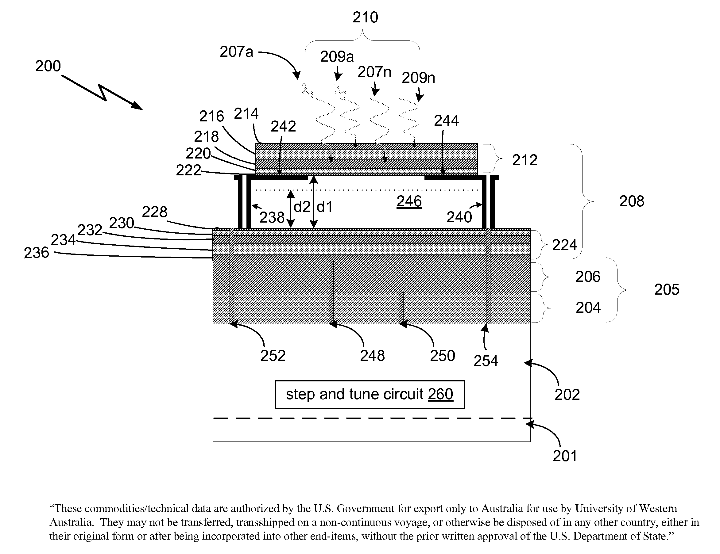
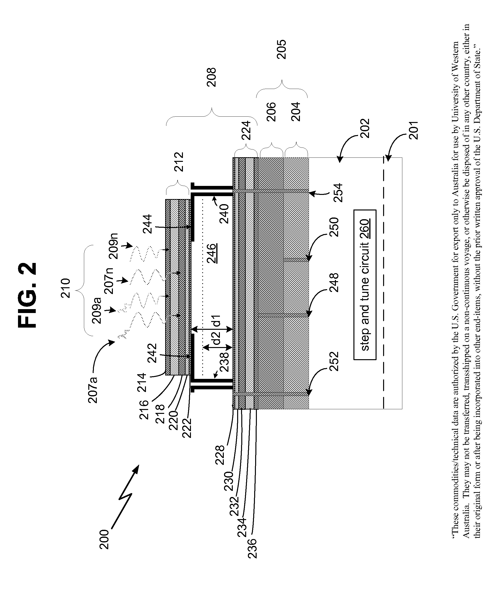
[0016]FIG. 2 is a front cross sectional view of an exemplary structure for each tunable infrared detector 200aa-200nn. Each tunable infrar...


PUM


Abstract

A tunable infrared detector is provided that includes a substrate, a bottom wavelength detector formed over the substrate, a top wavelength detector formed over the first wavelength detector layer, and an interferometer filter formed over the top wavelength detector layer and the bottom wavelength detector layer. The interferometer filter is operatively configured to pass a first wavelength associated with a first portion of a predetermined band and a second wavelength associated with a second portion of the predetermined band to the top wavelength detector. The top wavelength detector is operatively configured to detect each wavelength associated with the first portion of the predetermined band and to transmit each wavelength associated with the second portion of the predetermined band to the bottom wavelength detector. The bottom wavelength detector is operatively configured to detect each wavelength associated with the second portion of the predetermined band.

Description

STATEMENT OF GOVERNMENT INTERESTS[0001]“Technical data” that may be disclosed in this application is (at the date of filing of the application) authorized by the U.S. Government for export only to Australia for use by the University of Western Australia in accordance with Agreement No. TA 2039-03 IAW and 22 CFR 125.4(b)(2).FIELD OF THE INVENTION[0002]The present invention relates to image sensors, more particularly, to a spectrally tunable infrared image sensor having multi-band stacked detectors.BACKGROUND OF THE INVENTION[0003]The current generation of hyperspectral imaging (HSI) systems for use in the infrared wavelength bands employ a focal plane array (FPA) with a broad spectral response, integrated in a diffraction grating based on a Fourier transform spectrometer. An HSI system would be more widely deployable and available for applications if the system is miniaturized into a small package in an integrated microsystem without sacrificing the performance that existing systems ...

Claims


Application Information

Patent Timeline
IPC IPC(8): G01J5/02G01B9/02
CPCG01J3/26G01J3/36G01J3/2823
Inventor MITRA, PRADIPROBINSON, JAMES E.DELL, JOHN M.MUSCA, CHARLIE A.FARAONE, LAURIE
Owner DRS NETWORK & IMAGING SYST
Why Eureka
Try Eureka