Permanent-magnet-type rotating electrical machine

a permanent magnet and rotating electrical machine technology, applied in the direction of magnetic circuits, dynamo-electric machines, electrical apparatus, etc., can solve the problems of increasing the limit of the voltage reduction achieved, reducing the output and efficiency of the permanent magnet rotating electrical machine in a low-speed zone, and insulating breakage, so as to improve efficiency and reliability, high torque, and high output

Active Publication Date: 2009-09-24
KK TOSHIBA
View PDF22 Cites 57 Cited by
  • Summary
  • Abstract
  • Description
  • Claims
  • Application Information

AI Technical Summary

Benefits of technology

[0012]The present invention can provide the permanent-magnet-type rotating electrical machine capable of conducting a variable-speed operation in a wide range from lo...

Problems solved by technology

The voltage induced by the permanent magnets is applied to electronic parts of an inverter, and if the applied voltage exceeds a withstand voltage of the electronic parts, the parts will cause insulation breakage.
Such a design, however, lowers the output and efficiency of the permanent-magnet-type rotating electrical machine in a low-speed zone.
Such a voltage increase limits the voltage reduction achieved by the flux-weakening control.
These factors make it diffi...

Method used


Image

  • Permanent-magnet-type rotating electrical machine
  • Permanent-magnet-type rotating electrical machine
  • Permanent-magnet-type rotating electrical machine

Examples


first embodiment

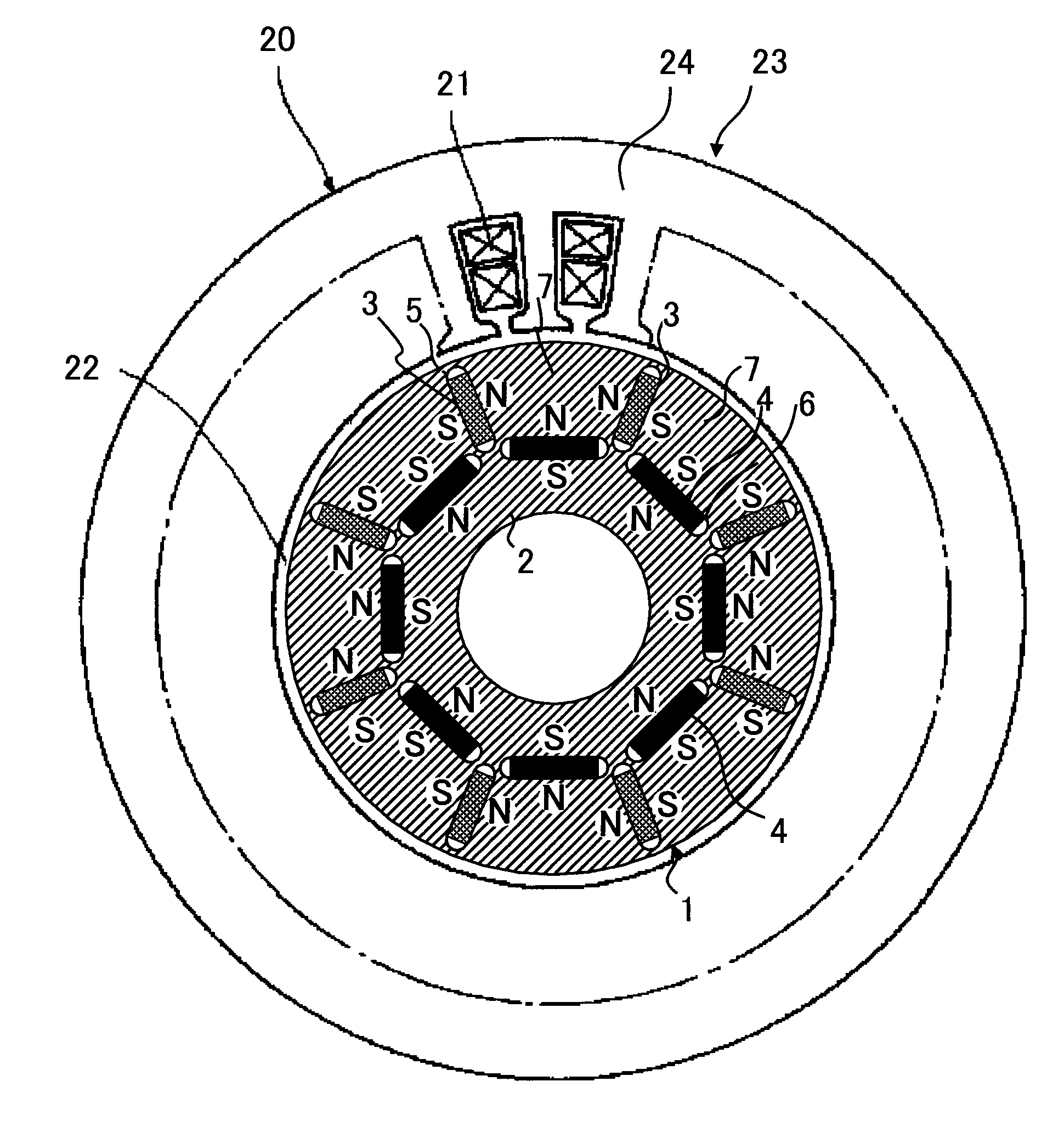
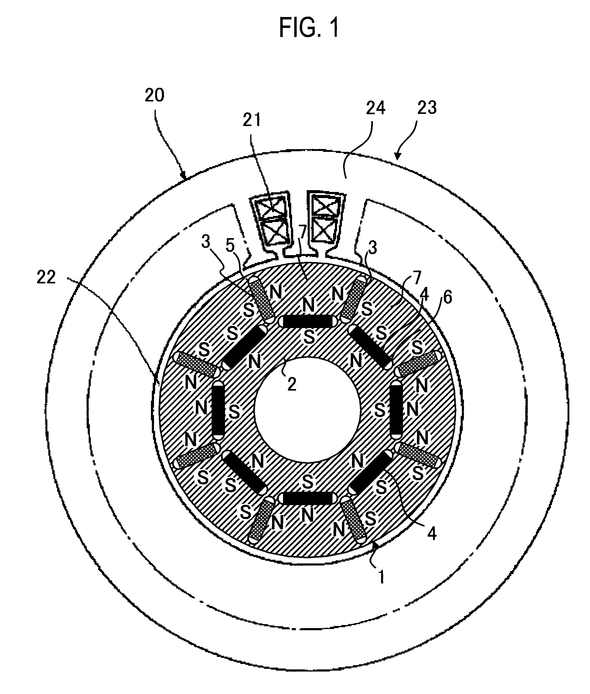
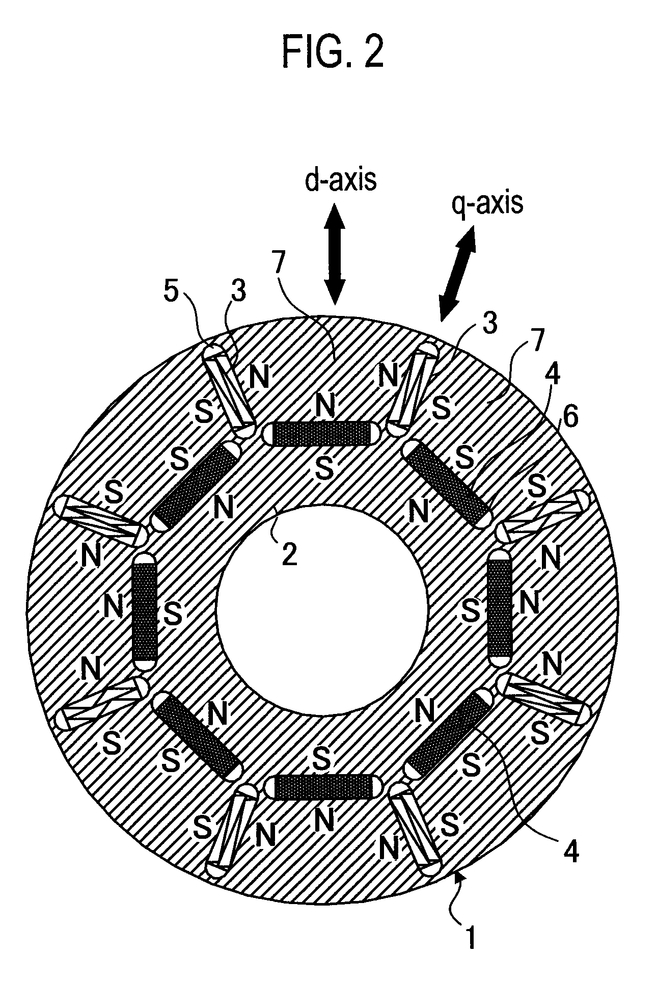
[0034]As illustrated in FIGS. 1 and 2, a permanent-magnet-type rotating electrical machine 20 according to the first embodiment of the present invention has a rotor 1. The rotor 1 has a rotor core 2 in which eight low-coercive-force permanent magnets 3 and eight high-coercive-force permanent magnets 4 are embedded at equal pitches. At a location of the rotor core 2 where the low-coercive-force permanent magnet 3 is embedded, a first hollow 5 is formed at each end of the permanent magnet 3. At a location of the rotor core 2 where the high-coercive-force permanent magnet 4 is embedded, a second hollow 6 is formed at each end of the permanent magnet 4. “7” indicates a magnetic pole portion of the rotor core 2. The rotor core 2 is constituted by laminating silicon steel plates. The low-coercive-force permanent magnet 3 is an alnico magnet or a FeCrCo magnet. The high-coercive-force magnet 4 is an NdFeB magnet.

[0035]As illustrated in FIG. 1, a stator 23 is constituted by winding a stator...

second embodiment

[0051]A rotating electrical machine 20 according to a second embodiment of the present invention is characterized in that, when a rotor 1 is at a highest rotation speed, a counter electromotive voltage generated by high-coercive-force permanent magnets 4 of the rotor is suppressed below a withstand voltage of electronic parts of an inverter serving as a power source of the rotating electrical machine.

[0052]A counter electromotive voltage caused by permanent magnets increases in proportion to rotation speed. If the counter electromotive voltage is applied to electronic parts of an inverter and if it exceeds a withstand voltage of the electronic parts, the electronic parts will cause insulation breakage. For this, a conventional permanent-magnet-type rotating electronic machine is designed to comply with the withstand voltage by reducing the flux amount of permanent magnets. This, however, deteriorates the output and efficiency of the motor in a low-speed zone.

[0053]According to the r...

third embodiment

[0055]A permanent-magnet-type rotating electrical machine 20 according to a third embodiment of the present invention is characterized in that, with permanent magnets providing a maximum flux amount to generate maximum torque, a flux amount of high-coercive-force permanent magnets 4 is smaller than a maximum flux amount of low-coercive-force permanent magnets 3.

[0056]When the rotating electrical machine provides the maximum torque, the flux amount of the low- and high-coercive-force permanent magnets 3 and 4 of a rotor 1 is maximized to reduce a necessary current and improve efficiency. At a maximum rotation speed, a d-axis current is passed to generate a magnetizing field to nearly zero the flux amount of each low-coercive-force permanent magnet 3, thereby nearly zeroing a counter electromotive voltage caused by the low-coercive-force permanent magnets 3. At the same time, each high-coercive-force permanent magnet 4 whose flux amount is not adjustable is designed to suppress its co...


PUM


Abstract

An object of the present invention is to provide a permanent-magnet-type rotating electrical machine capable of realizing a variable-speed operation at high output in a wide range from low speed to high speed and improving efficiency and reliability. The permanent-magnet-type rotating electrical machine of the present invention includes a stator provided with a coil and a rotor in which there are arranged a low-coercive-force permanent magnet whose coercive force is of such a level that a magnetic field created by a current of the stator coil may irreversibly change the flux density of the magnet and a high-coercive-force permanent magnet whose coercive force is equal to or larger than twice that of the low-coercive-force permanent magnet. At the time of high-speed rotation with a voltage of the permanent-magnet-type rotating electrical machine being around or over a power source maximum voltage, the low-coercive-force permanent magnet is magnetized with a magnetic field created by a current in such a way as to decrease total linkage flux of the low- and high-coercive-force permanent magnets, thereby adjusting a total linkage flux amount.

Description

TECHNICAL FIELD[0001]The present invention relates to a permanent-magnet-type rotating electrical machine.BACKGROUND TECHNOLOGY[0002]Generally, permanent-magnet motors are classified into two types. One is a surface-magnet-type motor having permanent magnets adhered to an outer circumference of a rotor core and the other is an internal-magnet-type motor having permanent magnets embedded in a rotor core. For a variable-speed drive motor, the internal-magnet-type motor is appropriate.[0003]With reference to FIG. 19, a structure of a rotor of the internal-magnet-type motor will be explained. In FIG. 19, 11 is the rotor, 12 is a rotor core, and 14 is a high-coercive-force permanent magnet. An outer circumferential area of the rotor core 12 is provided with rectangular hollows at regular pitches, the number of the hollows being equal to the number of magnetic poles. The rotor 11 illustrated in FIG. 19 has four poles, and therefore, four hollows are formed and the permanent magnets 14 are...

Claims


Application Information

Patent Timeline
IPC IPC(8): H02K21/16
CPCH02K1/2766H02K21/16H02K29/03
Inventor SAKAI, KAZUTOARATA, MASANORI
Owner KK TOSHIBA
Why Eureka
Try Eureka