
Inkjet recording head, inkjet recording device, and method for manufacturing the inkjet recording head

a technology of inkjet recording and inkjet printing, which is applied in the direction of electrical transducers, piezoelectric/electrostrictive/magnetostrictive devices, printing, etc., can solve the problems of achieve higher etching selectivity, prevent clogging of nozzle openings, and achieve the effect of etching more easily

Inactive Publication Date: 2009-09-24
SEIKO EPSON CORP
View PDF5 Cites 16 Cited by
  • Summary
  • Abstract
  • Description
  • Claims
  • Application Information

AI Technical Summary

Benefits of technology

[0007]An advantage of the invention is to provide a method for manufacturing an inkjet recording head that prevents clogging of nozzle openings caused by the adhesives, as well as to provide the inkjet recording head and an inkjet recording device.
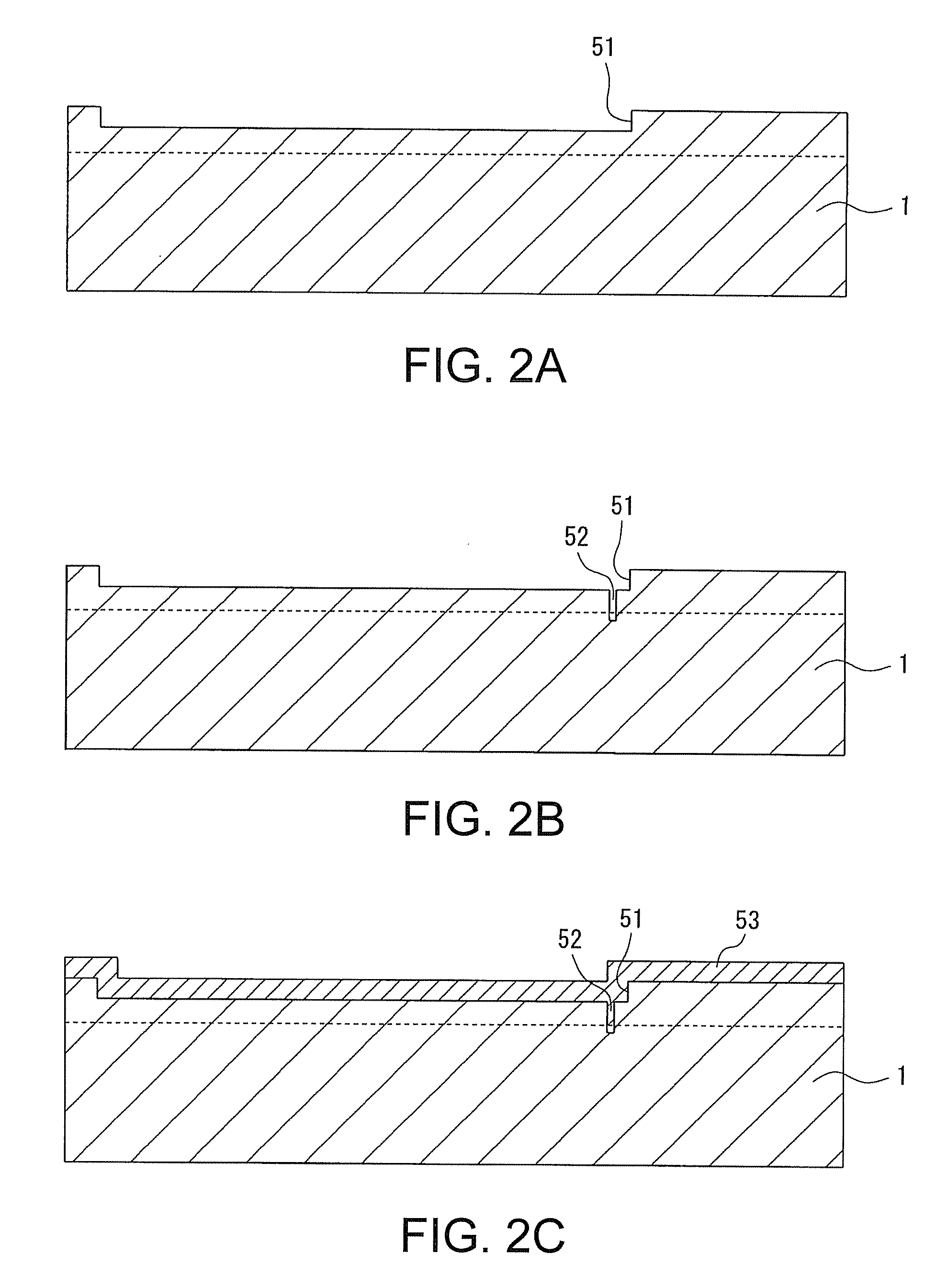
[0008]According to a first aspect of the invention, in a method for manufacturing an inkjet recording head which includes a pressure generation chamber supplied with ink fluid and a nozzle opening leading to the pressure generation chamber, the method includes: (a) forming a first trench which serves as the pressure generation chamber on a first surface of a first substrate; (b) forming a second trench which serves as the nozzle opening on a bottom surface of the first trench; (c) forming a sacrificial film on the first trench and the second trench; (d) forming a diaphragm on the sacrificial film as well as on the first surface of the first substrate; (e) forming a piezoelectric element on the diaphragm; (f) grinding a second surface of the first substrate so as to open a bottom surface of the second trench; (g) forming an opening which exposes the sacrificial film on the first surface of the first substrate; and (h) removing the sacrificial film through the opening.
[0009]Here, it is preferable to use a film with higher etching selectivity relative to that of the first substrate as the sacrificial film (in other words, a film which is etched more easily than the first substrate). For instance, if the first substrate is made of silicon (Si), then the sacrificial film may either be a silicon oxide film (SiO2) or a silicon germanium (SiGe) film. An example of the SiO2 film as the sacrificial film may also include a phosphosilicate glass (PSG) film that has a relatively fast etching rate.
[0010]In this case, the method for manufacturing an inkjet recording head may further include (i) bonding a second substrate that has a recess in an area facing the piezoelectric element to the first surface of the first substrate, so as to seal the piezoelectric element in the recess.
[0011]In this case, the method for manufacturing an inkjet recording head may further include forming, in the second substrate, a reservoir that leads to the pressure generation chamber.
[0012]In this case, the method for manufacturing an inkjet recording head may further include (k) forming an integrated circuit on a bottom surface of the recess prior to step (i).

Problems solved by technology

The methods disclosed above, however, may result in clogging of the nozzle openings due to the adhesives protruding beyond the bonding surface.

Method used


Image

  • Inkjet recording head, inkjet recording device, and method for manufacturing the inkjet recording head
  • Inkjet recording head, inkjet recording device, and method for manufacturing the inkjet recording head
  • Inkjet recording head, inkjet recording device, and method for manufacturing the inkjet recording head

Examples


Embodiment Construction

[0031]An embodiment of the invention will now be described with references to the accompanying drawings. Elements with the same structure described in the below drawings are denoted by the same numerical symbols, and the descriptions thereof are omitted.

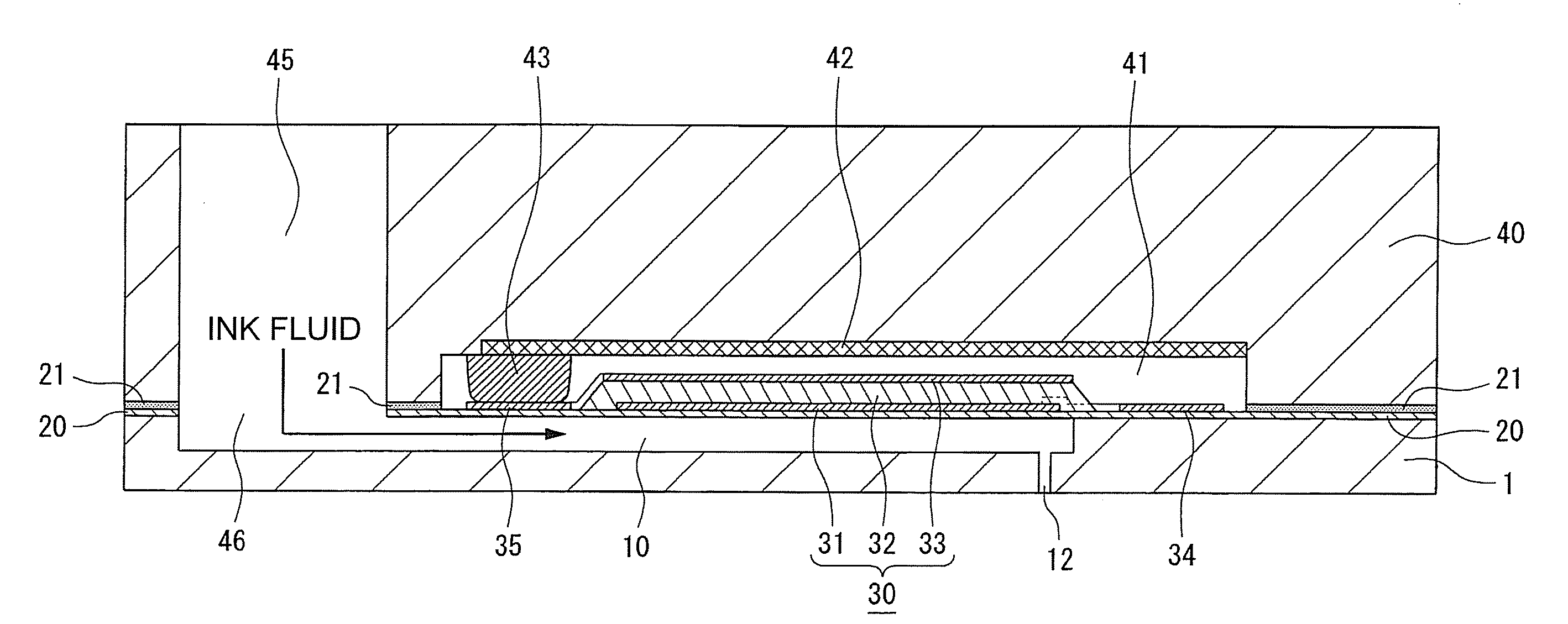
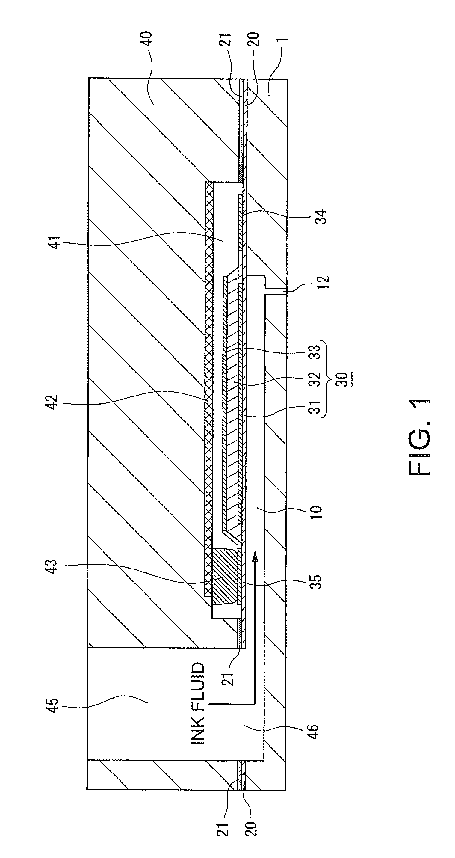
[0032]FIG. 1 is a sectional drawing illustrating a structural example of an inkjet recording head 100 according to an embodiment of the invention. As shown in FIG. 1, this inkjet recording head 100 includes, for instance, a substrate 1, a diaphragm 20, a piezoelectric element (i.e. piezo element) 30, and a sealing plate 40 that has a recess 41 in an area that faces the piezoelectric element 30.

[0033]The substrate 1 is a bulk silicon substrate with, for instance, a plane orientation of (100). This substrate 1 has, for instance, a thickness ranging from 150 μm to 1 mm, and includes a plurality of ink channels each formed as a separate compartment. Here, each of the ink channels is a route in which an ink fluid flows, and includes, as a...


PUM

PropertyMeasurementUnit
Pressureaaaaaaaaaa
Areaaaaaaaaaaa

Abstract

In a method for manufacturing an inkjet recording head which includes a pressure generation chamber supplied with ink fluid and a nozzle opening leading to the pressure generation chamber, the method includes: (a) forming a first trench which serves as the pressure generation chamber on a first surface of a first substrate; (b) forming a second trench which serves as the nozzle opening on a bottom surface of the first trench; (c) forming a sacrificial film on the first trench and the second trench; (d) forming a diaphragm on the sacrificial film as well as on the first surface of the first substrate; (e) forming a piezoelectric element on the diaphragm; (f) grinding a second surface of the first substrate so as to open a bottom surface of the second trench; (g) forming an opening which exposes the sacrificial film on the first surface of the first substrate; and (h) removing the sacrificial film through the opening.

Description

BACKGROUND[0001]1. Technical Field[0002]The present invention relates to an inkjet recording head, methods for manufacturing the same, and an inkjet recording device, particularly to techniques which prevent clogging of nozzle openings caused by adhesives.[0003]2. Related Art[0004]As shown in FIG. 7A, an inkjet recording head 200 according to an example of related art includes a piezoelectric element (in other words, piezo element) 201, a driver circuit 203 for driving the piezoelectric element, a sealing plate 205 for sealing the piezoelectric element, a reservoir 207 that is externally supplied with ink fluid, a substrate 210 having a diaphragm 209 and a pressure generation chamber 211, and a nozzle plate 220 in which a nozzle opening 213 is formed. As shown in FIG. 7B, the above components are bonded together with an adhesive, and the piezoelectric element 201 and the driver circuit 203 are connected with wire bonding, thereby building up this inkjet recording head 200.[0005]In r...

Claims


Application Information

Patent Timeline
IPC IPC(8): B41J2/135H01L41/22B41J2/045B41J2/055B41J2/14B41J2/16
CPCB41J2/14233B41J2/161B41J2/1623B41J2/1628B41J2/1629B41J2/1631Y10T29/42B41J2/1639B41J2/1642B41J2/1645B41J2/1646B41J2002/14241B41J2002/14491B41J2/1632
Inventor KANEMOTO, KEI
Owner SEIKO EPSON CORP
Learn More