Method for detecting a fibrous web tear in a drying section of a machine for producing the fibrous web and apparatus for performing said method

a drying section and fibrous web technology, applied in the field of fibrous web tear detection in the drying section of the machine for producing the fibrous web, can solve the problems of unsuitable light barriers, unreliable, and inability to distinguish clearly between the fibrous web and the dryer fabri

Inactive Publication Date: 2009-09-24
VOITH PATENT GMBH
View PDF8 Cites 6 Cited by
  • Summary
  • Abstract
  • Description
  • Claims
  • Application Information

AI Technical Summary

Benefits of technology

[0024]So that the inventive method can be used in as many applications as possible, including different applications if required, at least one filter can be installed between the luminous source and the detector of the optical device. The use of at least one filter permits major measurement modifications in return for only minor c...

Problems solved by technology

However, light barriers are unsuitable in situations in which the fibrous web rests on a skin acting as a web carrier, for example on a forming mesh, a press felt or a dryer fabric.
A drawback of the color detection system is that it becomes more and more unreliable as the color difference between the fibrous web and the dryer fabric decreases.
Here it is no longer possible to differentiate clearly between the fibrous web and the dryer fabric.
The former leads to an unnecessary stoppage of production and hence to financial loss for the plant operator, the latter runs the risk of causing damage to the machine.
Furthermore, dryer fabrics can become severely soiled the longer they are used, as the result of which the actual color of the dryer fabric is covered by dirt deposits.
In such cases also it has been discovered that a color detection system no longer works reliably.
It has been discovered that pseudo-structure detection systems likewise do not work reliably.
Narrow-band detection often results in o...

Method used


Image

  • Method for detecting a fibrous web tear in a drying section of a machine for producing the fibrous web and apparatus for performing said method
  • Method for detecting a fibrous web tear in a drying section of a machine for producing the fibrous web and apparatus for performing said method
  • Method for detecting a fibrous web tear in a drying section of a machine for producing the fibrous web and apparatus for performing said method

Examples


Embodiment Construction

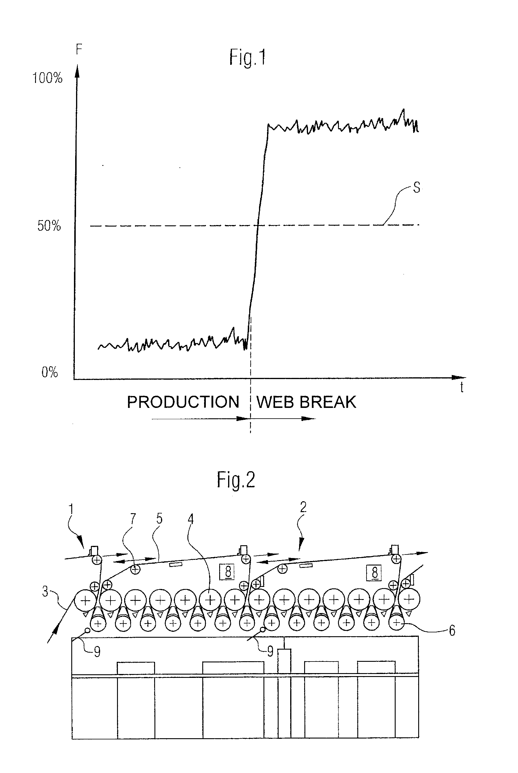
[0037]Referring now to the drawings, and more particularly to FIG. 2, there is shown schematically a side view of a detail of a drying section 2 of a machine, generally designated by 1, for producing a fibrous web 3.

[0038]Within the machine 1, the drying section 2 performs in known manner the function of removing moisture from a produced and / or processed fibrous web 3, meaning the function of drying it.

[0039]This is done in the example shown in FIG. 2 by way of contact drying, whereby a fibrous web 3 fed from the left in the drawing is dried by direct contact with a plurality of drying cylinders 4 on the one hand and an endless dryer fabric 5 circulating around the drying cylinders 4 on the other hand.

[0040]Presented in FIG. 2 are two dryer fabrics 5 in their complete path of rotation, whereby each of the dryer fabrics 5 circulates respectively around one group of drying cylinders 4. To be more precise, each dryer fabric 5 undulates in the region of the drying cylinders 4, whereby a...


PUM


Abstract

This invention relates to a method for detecting a tear in a fibrous web in a drying section of a machine for producing the fibrous web, whereby the fibrous web is passed through the drying section by way of at least one dryer fabric, whereby the tear is detected by at least one optical web tear detection device, which includes at least one luminous source and one detector, and whereby a cut-off apparatus for the fibrous web is directly or indirectly activated by the web tear detection device. The optical web tear detection device is operated over an extended wave length range in order to detect a tear in the fibrous web reliably. In addition, the invention relates to an apparatus for performing the inventive method.

Description

BACKGROUND OF THE INVENTION[0001]1. Field of the Invention[0002]This invention relates to a method for detecting a fibrous web tear in a drying section of a machine for producing the fibrous web, whereby the fibrous web is passed through the drying section by way of at least one dryer fabric, whereby the tear is detected by at least one optical web tear detection device which has a luminous source and a detector, and whereby a cut-off apparatus for the fibrous web is directly or indirectly activated by the web tear detection device.[0003]In addition the invention relates to an apparatus for detecting a fibrous web tear in a drying section of a machine for producing the fibrous web, which is passed through the drying section by way of at least one dryer fabric, having at least one optical web tear detection device including a luminous source and a detector, and a cut-off apparatus for the fibrous web which is directly or indirectly activatable by the web tear detection device.[0004]2...

Claims


Application Information

Patent Timeline
IPC IPC(8): G01N21/84
CPCD21F7/04G01N21/8901D21G9/0036
Inventor BAUER, ARMINUBLACKER, DIETMAR
Owner VOITH PATENT GMBH
Why Eureka
Try Eureka