
Radio-Access Method, Related Radio Base Station, Mobile-Radio Network and Computer-Program Product Using an Assignment Scheme for Antennas' Sectors

Active Publication Date: 2009-09-24
TELECOM ITALIA SPA
View PDF12 Cites 42 Cited by
  • Summary
  • Abstract
  • Description
  • Claims
  • Application Information

AI Technical Summary

Benefits of technology

[0020]certain basic limitations as regards flexibility in the remote stations (e.g. enabling time alignment of the frames only as an advanced processing option) are dispensed with, thus improving the degree of reconfigurability of the network, including antenna reconfigurability,
[0022]improved flexibility is achieved in terms of use and of number of beacon channels that can be handled (as a whole, in terms of signal processing) as compared to conventional arrangements.
[0044]The exemplary arrangement described herein is thus an architecture including completely reconfigurable remotized stations, enabling a complete functionality of processing of the signal received and transmitted (in the two links of reception and transmission of the radio signal).

Problems solved by technology

A technical problem associated to the widespread use of microcells is linked to the service provided to high-mobility users.
A user who is moving at a high speed in a microcell context, in fact, carries out a very large number of handover procedures between the cells, which cause a signalling overload both on the uplink and on the downlink.
In addition to the signalling overload it should be recalled that associated to the operations of measurement and to the consequent operations for support of the mobility are processing delays, which, in the case of small cell dimensions, may prove critical for execution of the handoff procedures, with consequent possible drop of the call.
As highlighted in T. Ojampera, R. Prasad, “Wideband CDMA for Third Generation Mobile Communications”, Artech House, 1998, the use of a system with macrocells and microcells on the same W-CDMA carrier presents numerous problems of design and operation.
This condition can be caused, for example, by a delay in the handover procedures, as referred to previously, and brings about an increase in the interference suffered by the microcell and, consequently, a deterioration in the performance for all the users served by the microcell itself.
Frequently, however, UMTS operators have a very limited number of carriers available.
In the case where the operator has only two carriers available for example, this constraint results in an obligate choice, and prevents alternative solutions such as, in particular, the use of both of the carriers at the microcell level, which maximizes the overall capacity of the W-CDMA radio access.

Method used


Image

  • Radio-Access Method, Related Radio Base Station, Mobile-Radio Network and Computer-Program Product Using an Assignment Scheme for Antennas' Sectors
  • Radio-Access Method, Related Radio Base Station, Mobile-Radio Network and Computer-Program Product Using an Assignment Scheme for Antennas' Sectors
  • Radio-Access Method, Related Radio Base Station, Mobile-Radio Network and Computer-Program Product Using an Assignment Scheme for Antennas' Sectors

Examples


Embodiment Construction

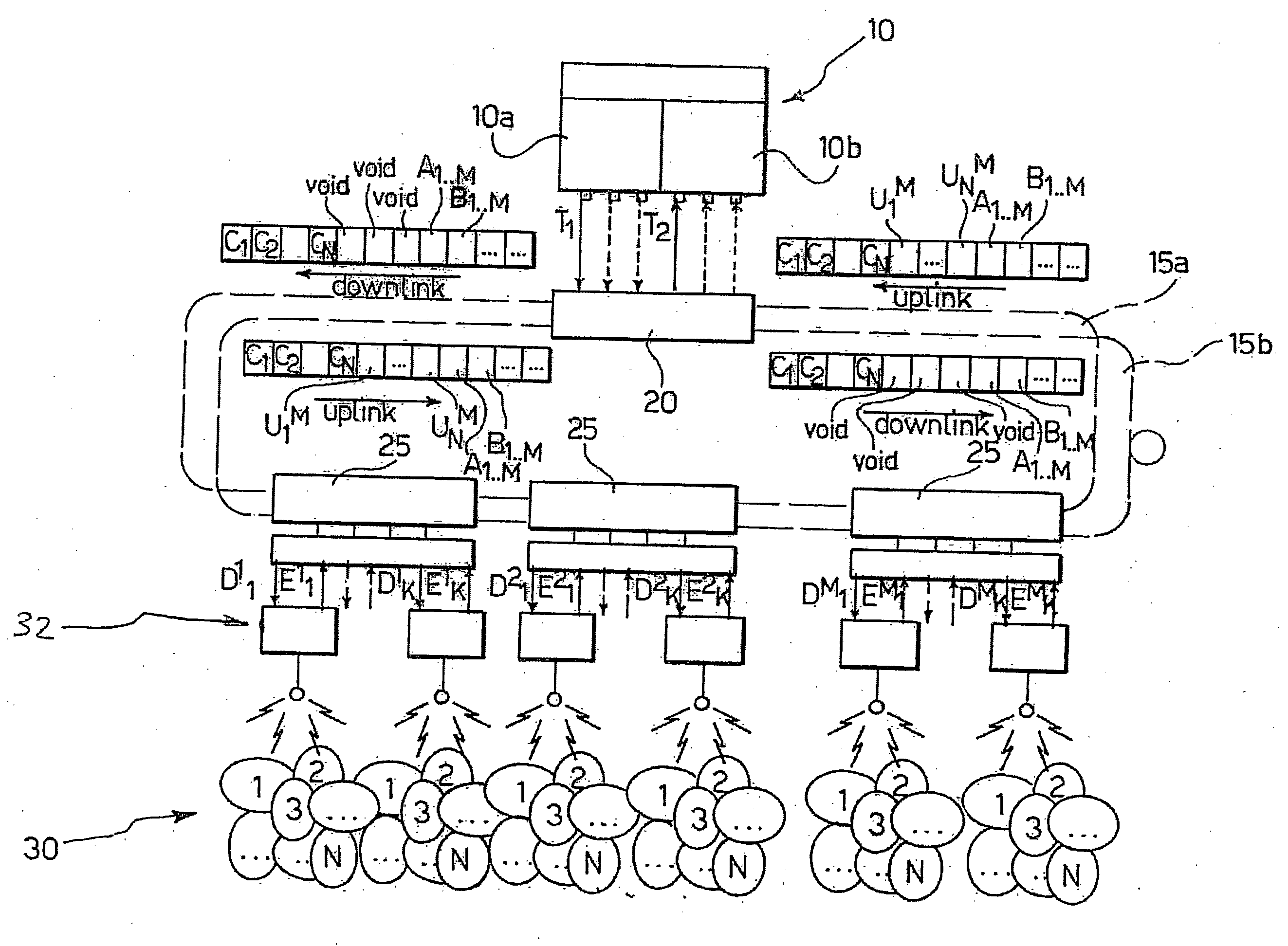
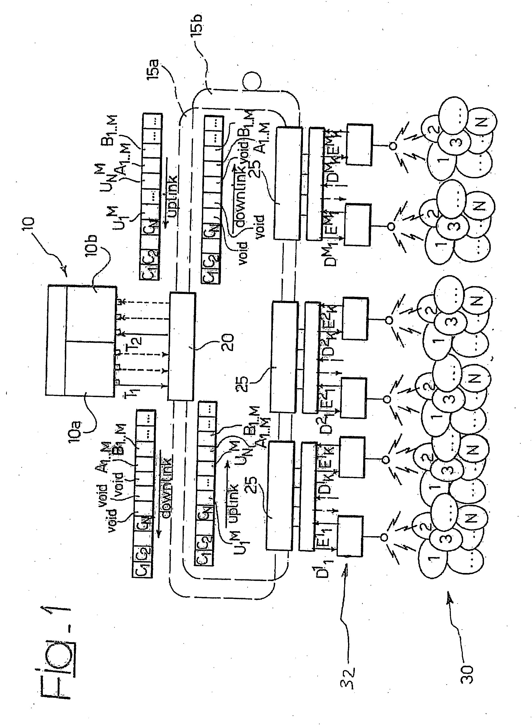
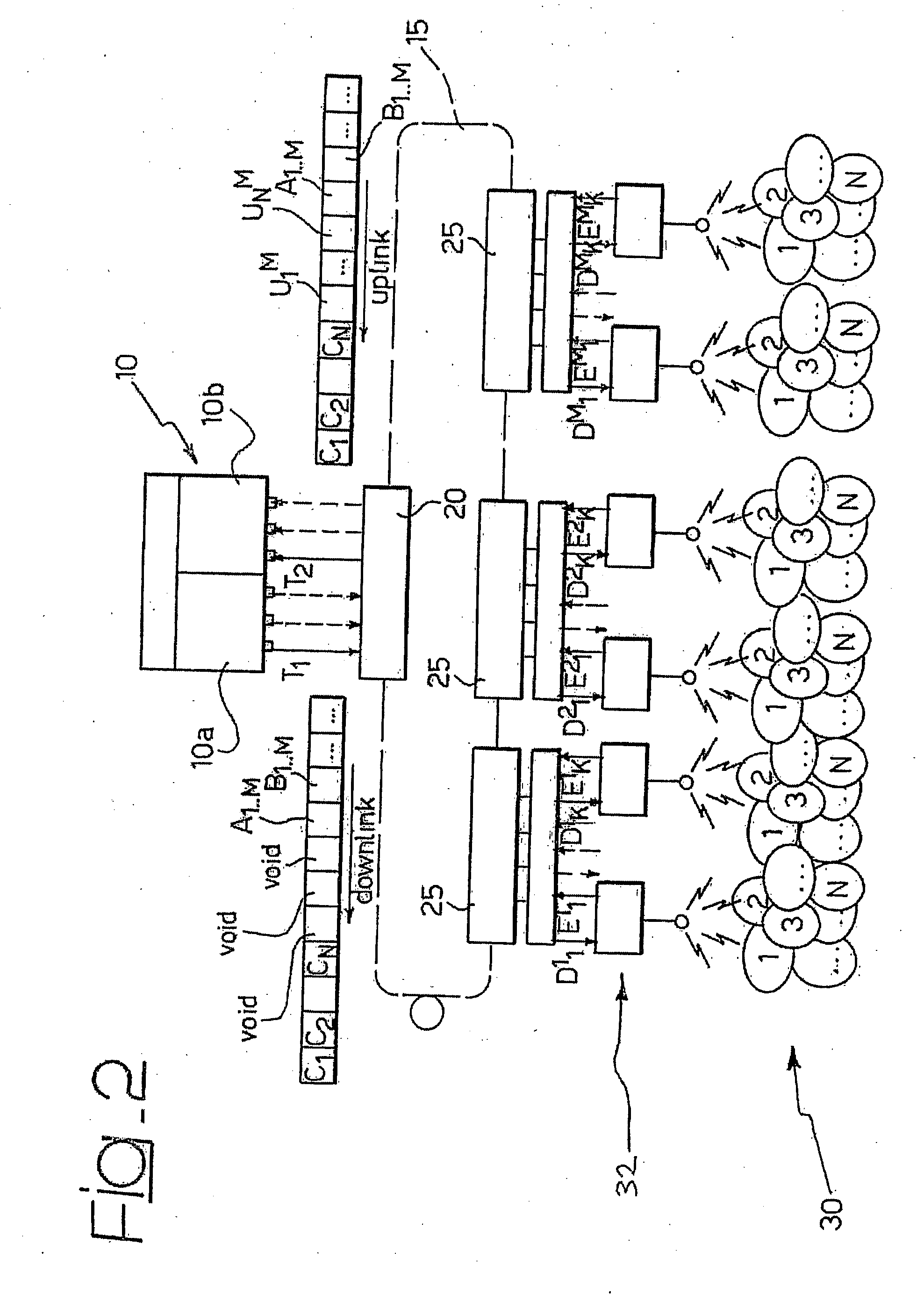
[0053]FIG. 1 provides an exemplary schematic representation of the architecture of a radio base station (BTS or Node B) in a mobile-radio network (not shown as whole). Specifically, a radio base station 10 is considered, which has an optical-to-digital interface with three data flows in the downlink and, accordingly, three data flows in the uplink.

[0054]The radio base station 10 (which may be in the form of a conventional BTS) comprises a subsystem 10a that handles transmission of the signals in the downlink for the three data flows, and a subsystem 10b, which comprises the apparatuses dedicated to reception of the signals in the uplink.

[0055]T1 represents the first of the three flows in the downlink and T2 the first of the three flows in the uplink. In the example considered, each flow is routed onto an optical-fibre ring 15a and 15b by means of an optical transmitter, in the downlink case, or optical receiver, in the uplink case. The flows can be routed on the same optical fibre 1...


PUM


Abstract

A radio base station for a mobile radio network, includes a set of remote units connected with the radio base station, preferably via a radio over fibre arrangement. Each remote unit provides radio cell coverage by means of a set of communication channels, and is equipped with a respective set of antenna elements. The communication channels are distributed over the antenna elements according to an assignment scheme that is dynamically variable.

Description

FIELD OF THE INVENTION[0001]The present invention relates to techniques for radio access in mobile-radio networks.[0002]The invention has been developed with particular attention paid to its possible use in networks employing distributed radio base stations.DESCRIPTION OF THE RELATED ART[0003]Mobile-radio systems must guarantee a service of communication between a telecommunications network and mobile terminals (user terminals) randomly distributed over a certain service area. The radio coverage of this area is obtained by installing a plurality of radio base stations, each of which has the task of covering a certain portion of the area, referred to as a cell, from which there derives the name “cellular systems”. The generic mobile terminal can communicate with the communications network through one of the radio base stations of the system, for example the one from which it receives the radio signal with best quality. The procedures through which the terminal, once it is turned on, ...

Claims


Application Information

Patent Timeline
IPC IPC(8): H04B10/20H04W72/04H04W88/08
CPCH04W88/085
Inventor BOLDI, MAUROGIANOLA, PAOLOQUASSO, ROBERTO
Owner TELECOM ITALIA SPA
Learn More