
Configuration of an Electronic Control System for Controlling the Operation of at Least One Component of a Vehicle

Inactive Publication Date: 2009-09-24
AIRMAX GROUP
View PDF8 Cites 49 Cited by
  • Summary
  • Abstract
  • Description
  • Claims
  • Application Information

AI Technical Summary

Benefits of technology

[0013]This object is achieved by the method according to embodiments of the invention, which is characterised by causing a programming unit on board the vehicle to programme the appropriate set into the programmable non-volatile memory. By obtaining sensor data pertaining to the vehicle during its operation, characteristics of the actual usage and operation or the vehicle can be deduced by analysing the sensor data. By determining an appropriate set of programme data based on the analysis, the performance of the vehicle component or components can be adapted to suit the determined characteristics. By causing a programming unit to programme the appropriate set into the programmable non-volatile memory, it is possible to use a bespoke set of data, allowing for better optimisation of the performance characteristics of the vehicle component to suit the actual conditions. Because it is the programme data read by the microcontroller from the programmable non-volatile memory (“Keep-Alive Memory”) that is adapted, a more radical adaptation can be effected than would be possible by modifying a limited set of variables that the microcontroller may maintain in registers (“scratch pad memory”) when controlling the at least one vehicle component. In effect, the control strategy can be modified. By causing a programming unit on board the vehicle to carry out the programming, adaptation to actual usage and operation of the vehicle are achievable. A further advantage is that such adaptation can be achieved without reducing the length of the service intervals of the vehicle.
[0023]This variant takes into account that a vehicle may have several regular operators. It allows for a separation of operator profiles, and contributes to improving the adaptation of the electronic control system.
[0027]An effect is to adapt the vehicle's performance most effectively to the conditions under which it is operated, since the engine performance has the greatest effect on the overall vehicle performance. Moreover, in particular in the case of internal combustion engines, the engine performance requires most adaptation to changing conditions. being relatively sensitive to changing conditions and determinative of many key performance indicators, such as fuel efficiency, speed, etc.
[0028]In a variant, determining an appropriate set of programme data includes establishing a set of programme data having an effect of improving the efficiency of the engine under conditions to be expected and determined in accordance with the analysis.
[0031]An effect is to be able to avoid flat spots and increase fuel economy by operating at close to optimum. In effect, it allows for the electronic control system to be adapted such that the accelerator pedal becomes a means of indicating required power, as opposed to a throttle control. This embodiment is based on the recognition of the fact that internal combustion engines achieve optimum specific fuel consumption at a certain percentage of their maximum output, not just at particular ranges of Revolutions Per Minute. An implementation would, for instance, include modifying a control strategy for selectively switching cylinders on and off, based on expected engine loads.
[0035]An effect is to help eliminate the dependency on the often limited maximum data rate of conventional on-board diagnostic systems. The standards for such systems are generally laid out to accommodate devices according to the lowest common denominator.

Problems solved by technology

A problem of the known method is that it is based on default assumptions regarding future usage of the vehicle.
The tuning pattern selected by the manager ECU offers limited scope for optimising the performance of the vehicle components to suit the actual operational needs.

Method used


Image

  • Configuration of an Electronic Control System for Controlling the Operation of at Least One Component of a Vehicle
  • Configuration of an Electronic Control System for Controlling the Operation of at Least One Component of a Vehicle
  • Configuration of an Electronic Control System for Controlling the Operation of at Least One Component of a Vehicle

Examples


first embodiment

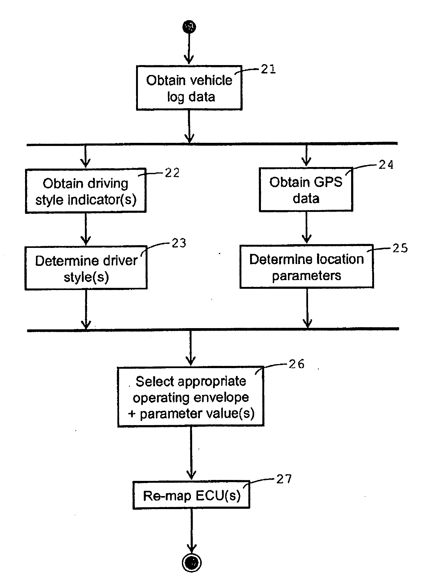
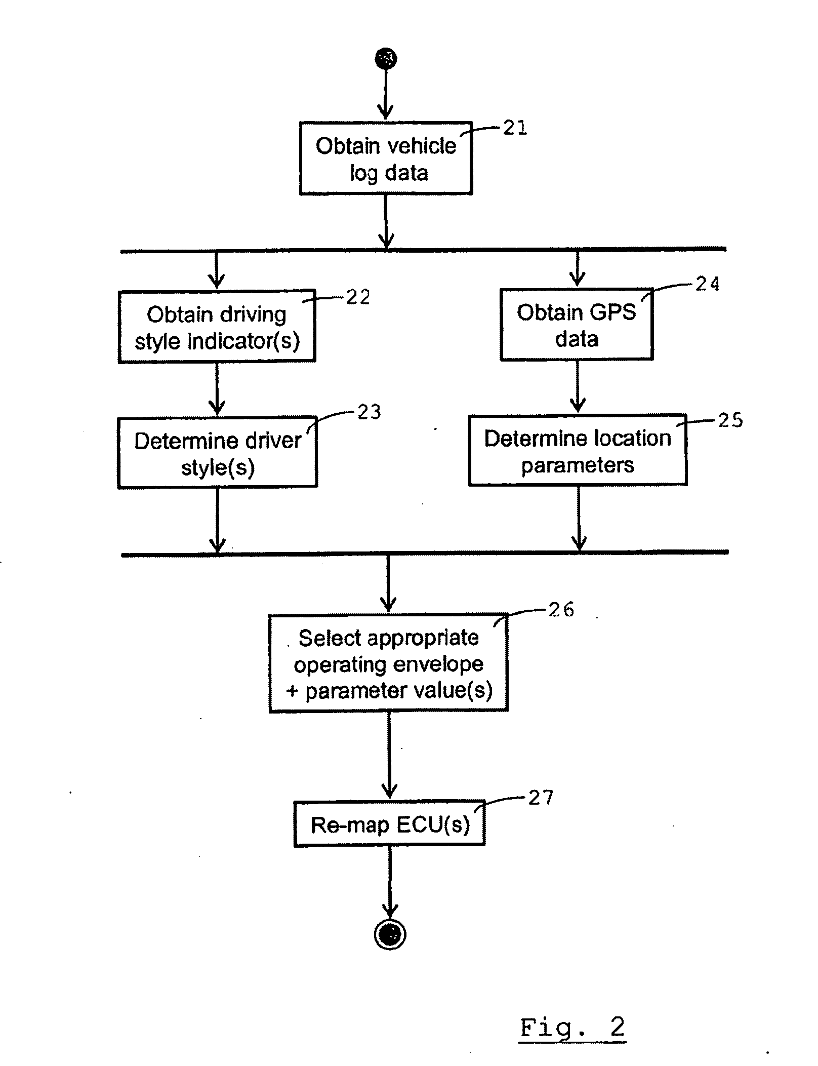
[0043]FIG. 3 is a simplified flow chart showing a step in the method of FIG. 2; and

second embodiment

[0044]FIG. 4 is a simplified flow chart showing a step in the method of FIG. 2.

DETAILED DESCRIPTION OF EXAMPLES OF EMBODIMENTS

[0045]Methods for configuring (including re-configuring) electronic control systems for vehicles are discussed herein using the example of a motor car 1. They are equally applicable to other types of vehicle, particularly motor vehicles, such as motor bikes, lorries, ships, aircraft, agricultural machinery, etc.

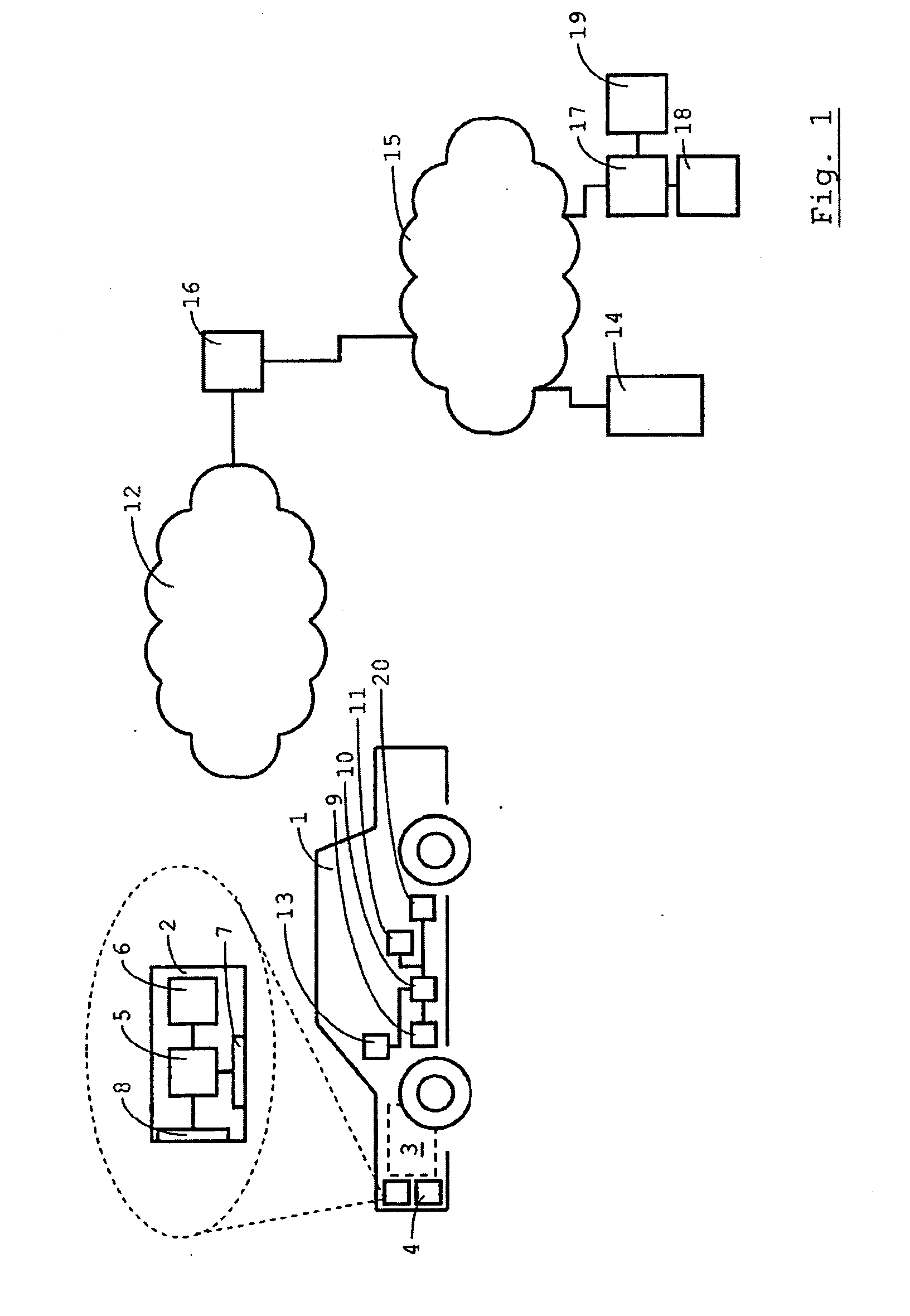
[0046]The car 1 includes an Engine Control Unit (ECU) 2 for controlling an internal combustion engine 3 and an electronic control unit 4 for an Electronic Stability Control (ESC) system (not shown in detail). Engine Control Units are also referred to as Power-Train Control Modules (PCM). The ECU 2 is essential to controlling electronic fuel injection. This description will focus on the ECU 2, but is equally applicable to the electronic control unit 4 of the ESC system. The ECU 2 includes a microcontroller 5 and programmable non-volatile memory, here in...


PUM


Abstract

An electronic control system for controlling the operation of at least one component of a vehicle includes: a microcontroller; programmable non-volatile memory, wherein the microcontroller is configured to process input signals from at least one vehicle sensor to provide output signals for controlling the at least one vehicle component in accordance with programme data read at least partly from the programmable non-volatile memory; and an interface enabling a programming unit to programme at least part of the programme data into the programmable non-volatile memory. A method of configuring the electronic control system includes: obtaining data based on sensor signals and pertaining to the vehicle during its operation; analysing the data based on sensor signals; determining an appropriate set of programme data based on the analysis; and causing a programming unit on board the vehicle to programme the appropriate set into the programmable non-volatile memory.

Description

CROSS-REFERENCE TO RELATED APPLICATIONS[0001]This application claims the benefit of British Patent Application No. 0802368.1, filed Feb. 8, 2008, which is incorporated herein by reference.FIELD OF THE INVENTION[0002]This invention relates generally to vehicles, and relates more particularly to controlling the operation of at least one component of a vehicle.DESCRIPTION OF THE BACKGROUND[0003]US 2001 / 0056318 describes an integrated vehicle control system for integratedly controlling a plurality or components such as an engine or an automatic transmission mounted on a vehicle. As component control sections, an engine ECU and an AT ECU arc provided. In the engine ECU and the AT ECU non-volatile memories (ROM) are provided. Stored in the memories in advance are the tuning freedom degree information, representing a category of tuning patterns settable on the side of the respective ECU, and the characteristic information representing the operation of the engine and the automatic transmiss...

Claims


Application Information

Patent Timeline
IPC IPC(8): G06F7/00B60W40/08B60W50/08
CPCB60W40/09B60W50/085G05B2219/2637G05B19/0426G05B2219/23297B60W2050/008B60W2556/65B60W2050/0075G05B11/00G05B11/01G05B13/024G05B15/02
Inventor DUDDLE, ASHLEY ROBERTPERHAM, STEPHAN HENRYMASON, LEE
Owner AIRMAX GROUP
Learn More