Nozzle plate of a spray apparatus and fabrication method thereof

Inactive Publication Date: 2009-10-01
IND TECH RES INST
View PDF8 Cites 7 Cited by
  • Summary
  • Abstract
  • Description
  • Claims
  • Application Information

AI Technical Summary

Benefits of technology

[0018]The main body of the nozzle plate is coupled to an actuator mounted to the main body with the actuator on the side with a liquid container so as to provide nebulization of the liquid placed in the liquid container. The inlet end and the outlet end of the nozzle of the main body are mirroring symmetrical and have a centroid with positional deviation from a pattern center so as to control the predetermined angle at which the liquid departs as well as the direction in which the liquid is propagated. Also, the geometry of the orifice design as well as the coordination of the overall orifice arrangement distribution are varied in accordance with the user's requirements, thereby allowing the liquid to be nebulized in the same direction at different angles of slanting, concentration or scattering so as to achieve the effect of enlarging the nebulizing area and obtain a more uniformly distributed nebulizing of the liquid. At the same time, varying the arrangement of the orifice distribution lowers the number of mutual collisions between nebulized liquid droplets without increasing the volume o

Problems solved by technology

This not only increases the size of the nebulized droplets but also diminishes the nebulizing effect.
As a consequence, both liquid and energy consumption will be increased.
Even though such a conventional technique increases the mist range, the larger spraying range of the orifices requires a higher operating frequency for the piezoelectric actuator, and, therefore, the energy consumed by driving the spray apparatus is also increased, leading to the disadvantage of excessive spray apparatus volume, which poses a problem of accumulation of the nebulized droplets.
However, the laser process is a technique that is unable to easily control the droplet propagation direction and the Japanese method is complicated, and thus the problems of a narrow nebulization range as well as ineffective nebulization are still not solved.
However, the aforementioned conventional technique creates a symmetrical design for the orifices employed by the nozzle plate of

Method used


Image

  • Nozzle plate of a spray apparatus and fabrication method thereof
  • Nozzle plate of a spray apparatus and fabrication method thereof
  • Nozzle plate of a spray apparatus and fabrication method thereof

Examples


first embodiment

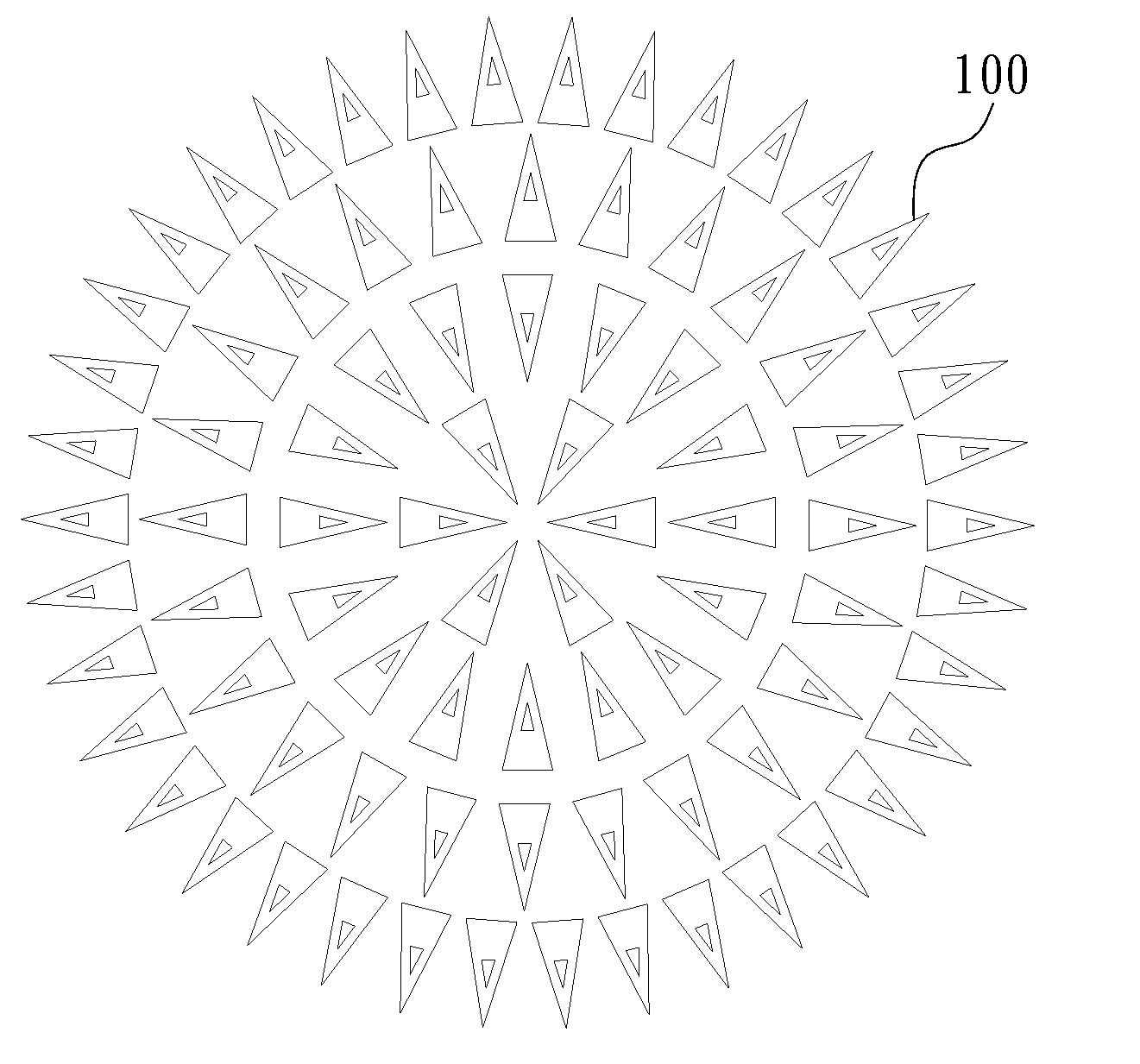
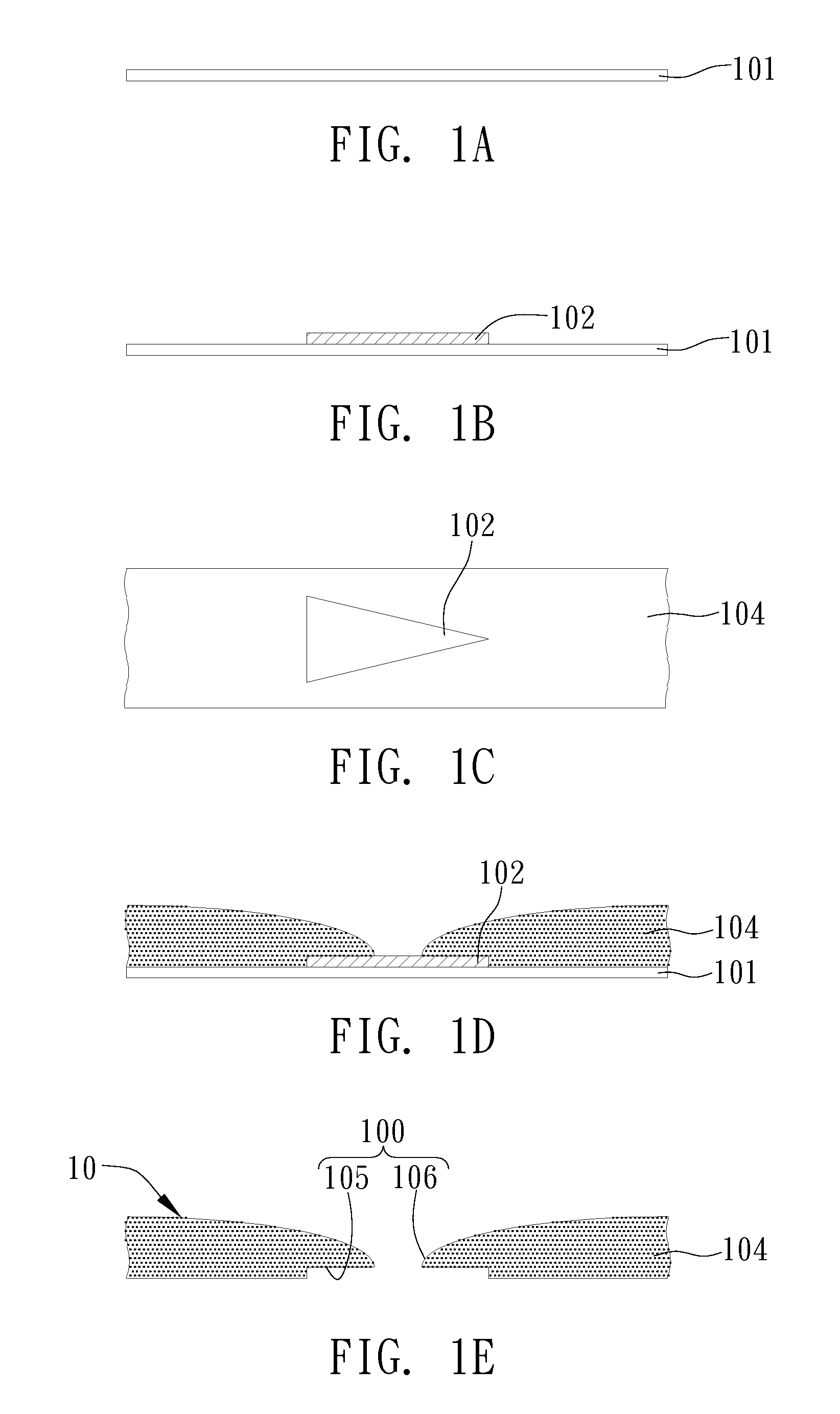
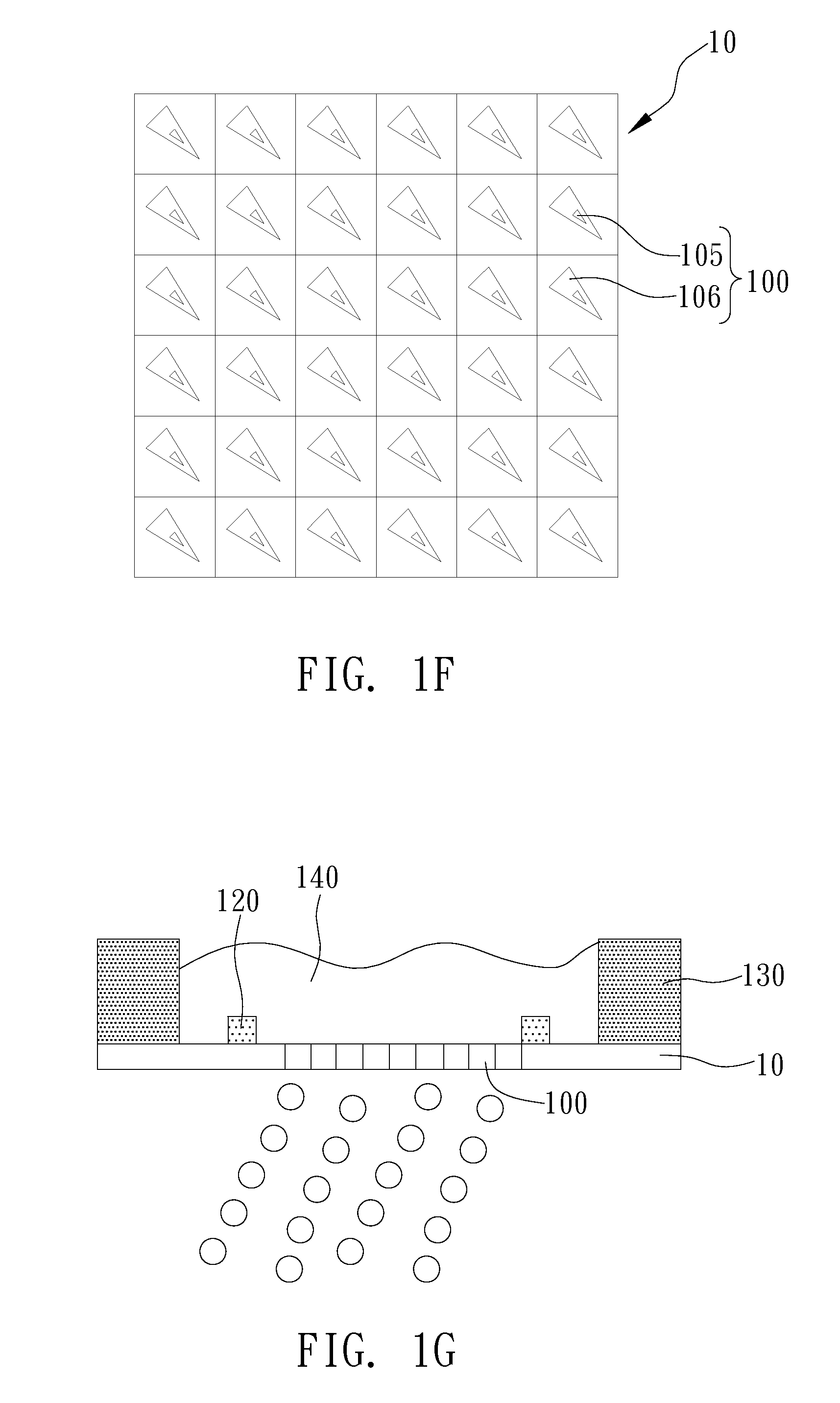
[0032]FIGS. 1A to 1G are diagrams depicting a main body of a nozzle plate of the present invention and the manufacturing method as well as illustrating an application of the nozzle plate on a spray apparatus according to the first embodiment. The nozzle plate of the present invention forms a spray apparatus in conjunction with an actuator 120, such as a piezoelectric actuator, and a liquid container 130. The nozzle plate is installed on one side of the liquid container 130, which is for containing a liquid 140 to be nebulized. The combination of the actuator 120 and the nozzle plate nebulizes the liquid 140 by vibrating the nozzle plate.

[0033]As shown in FIGS. 1A to 1C, an electrically conductive layer 101 is provided. A plurality of insulating layers 102 (only one is shown) is formed on the conductive layer 101. Subsequently, a pattern is defined on the insulating layer 102 by a photolithography process or a printing process, shaping the insulating layer 102 into a mirroring symmet...

second embodiment

[0039]Referring to FIGS. 3A to 3E, a second embodiment of a nozzle plate of a spray apparatus and its manufacturing method according to the present invention are illustrated. The second embodiment of the present invention is generally the same as the above-described first embodiment. The primary difference is that an insulating layer 102 further includes a first insulating layer 102a and a second insulating layer 102b. In other words, a plurality of the first insulating layers 102a is formed on a conductive layer 101, and a plurality of second insulating layers 102b with areas smaller than that of the first insulating layers 102a is respectively formed on top of the first insulating layers 102a. At the same time, a pattern is defined on the first insulating layer 102a and the second insulating layer 102b by a photolithography process or a printing process, allowing the first insulating layers 102a and the second insulating layers 102b to form mirroring symmetrical geometrical struct...

third embodiment

[0040]FIGS. 4A and 4B show a third embodiment of a nozzle plate of a spray apparatus of the present invention. As shown in the diagrams, the third embodiment is generally the same as the above-described first embodiment. The primary difference is that the tapered ends of the inlet ends 105 and the outlet ends 106 face the interior of the main body 10′, displacing the propagation direction D of the liquid 140 toward the base of the geometrical structure so as to control the propagation direction D of the nebulization of the liquid 140 such that the ejected liquid is scattered, thereby expanding the range of liquid nebulization.


PUM

PropertyMeasurementUnit
Structureaaaaaaaaaa
Electrical conductoraaaaaaaaaa
Areaaaaaaaaaaa

Abstract

A nozzle plate for use with a spray apparatus and a fabrication method thereof are provided. The nozzle plate has a plurality of orifices each including an inlet end and an outlet end. The inlet end and the outlet end have a geometrical structure with mirror symmetry and a centroid with positional deviation from a pattern center. The pattern center is the center of an imaginary circle circumscribed about the geometrical structure. The geometrical structure controls the propagation direction of liquid spray, expands the nebulizing range per unit density of orifices, enables product miniaturization, and saves energy.

Description

BACKGROUND OF THE INVENTION[0001]1. Field of the Invention[0002]The present invention relates to a liquid nebulizing (atomizing) technique, and more particularly, to a nozzle plate of a spray apparatus and its manufacturing method.[0003]2. Description of Related Art[0004]Liquid nebulizing systems have become more widely adopted in various applications such as drug delivery systems in the biomedical field, atomizing fuel for internal combustion engines in the automotive field as well as the heat radiation using liquid exchange in the HVAC field. All of the foregoing applications employ nebulization theory and examples of relevant patents include U.S. Pat. Nos. 4,465,234, 4,605,167, 6,089,698, 6,235,177 and 6,629,646, Taiwanese Patent Numbers 407529, 449486, 503129, 506855 and 562704, as well as the Taiwanese Patent Cert. Number 1222899.[0005]Most of the conventional designs for the nozzle plate of the spray apparatus employ a piezoelectric actuator as a vibrator with a matched nozzle...

Claims


Application Information

Patent Timeline
IPC IPC(8): B05B17/06B05B1/14B21D53/00
CPCB05B17/0646Y10T29/49401C25D1/08C25D5/022B41J2/135B41J2/164C25D5/02Y10T29/49128Y10T29/49155B41J2/162B41J2/1625B41J2/1643C25D5/16C25D5/22Y10T29/496B05B17/0661
Inventor LU, CHUN-FU
Owner IND TECH RES INST
Why Eureka
Try Eureka