Speed reducer for use in yaw drive apparatus for wind power generation apparatus, and yaw drive method and apparatus for wind power generation apparatus using the speed reducer

a technology of speed reducer and yaw drive, which is applied in the direction of motor/generator/converter stopper, dynamo-electric converter control, gearing, etc., can solve the problems of significant impact on the first gear, the teeth of the first and second gears may be damaged, and the inability to rotate by following the second gear, etc., to achieve the effect of reducing the damage on the teeth, reducing the size of the apparatus and low pri

Active Publication Date: 2009-10-01
NABLESCO CORP
View PDF77 Cites 13 Cited by
  • Summary
  • Abstract
  • Description
  • Claims
  • Application Information

AI Technical Summary

Benefits of technology

[0012]In consideration of the above-described situation, it is an object of the present invention to provide a speed reducer which is provided with an optimum speed distribution for a yaw drive apparatus, has high efficiency and a short axial length, and is suitable for the yaw drive apparatus. Further, it is another object of the present invention to provide a yaw drive apparatus of a wind power generation apparatus which is highly efficient and is compact in size.

Problems solved by technology

However, since the wind power generation unit has a large inertial mass, it cannot rotate by following the second gear.
As a result, the teeth of the second gear cause a significant impact on the first gear.
Therefore, the teeth of the first and second gear may be damaged at the start-up of the yawing of the wind power generation unit, or a loud noise occurs.
Further, considering the structural features, the strength of the first and second gears needs to be increased for the impact resistance, so that the apparatus becomes expensive and large in size.
However, since the wind power generation unit is apt to rotate continuously at the same rotational speed, the teeth of the first gear cause a significant impact on the teeth of the second gear.
Therefore, the teeth of the first and second gear may be damaged even when the yawing of the wind power generation unit is stopped, or a loud noise occurs.
Further, the strength of the first and second gears needs to be increased for the impact resistance as described above, thus the apparatus becomes expensive and large in size.

Method used


Image

  • Speed reducer for use in yaw drive apparatus for wind power generation apparatus, and yaw drive method and apparatus for wind power generation apparatus using the speed reducer
  • Speed reducer for use in yaw drive apparatus for wind power generation apparatus, and yaw drive method and apparatus for wind power generation apparatus using the speed reducer
  • Speed reducer for use in yaw drive apparatus for wind power generation apparatus, and yaw drive method and apparatus for wind power generation apparatus using the speed reducer

Examples


example 1

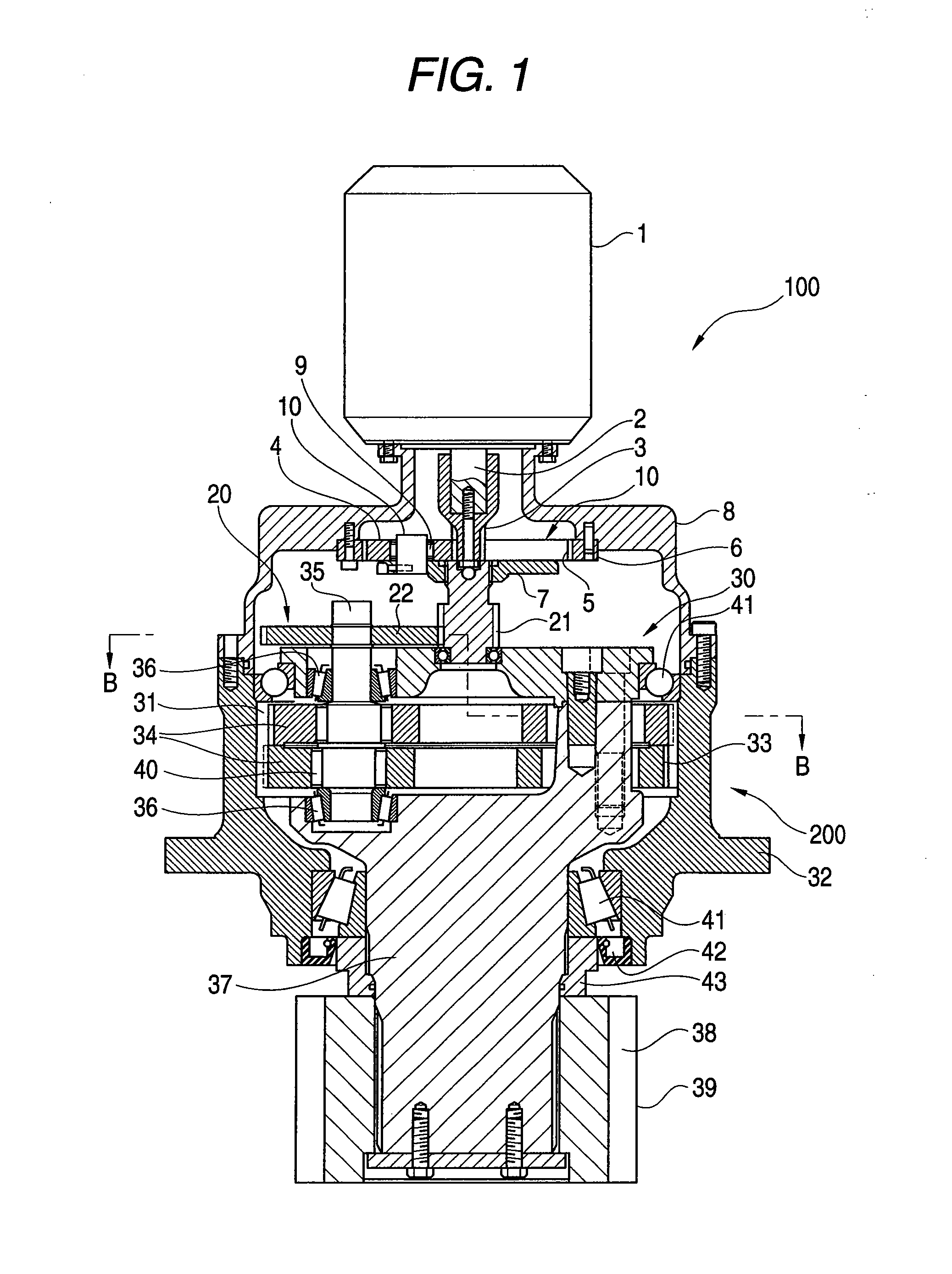
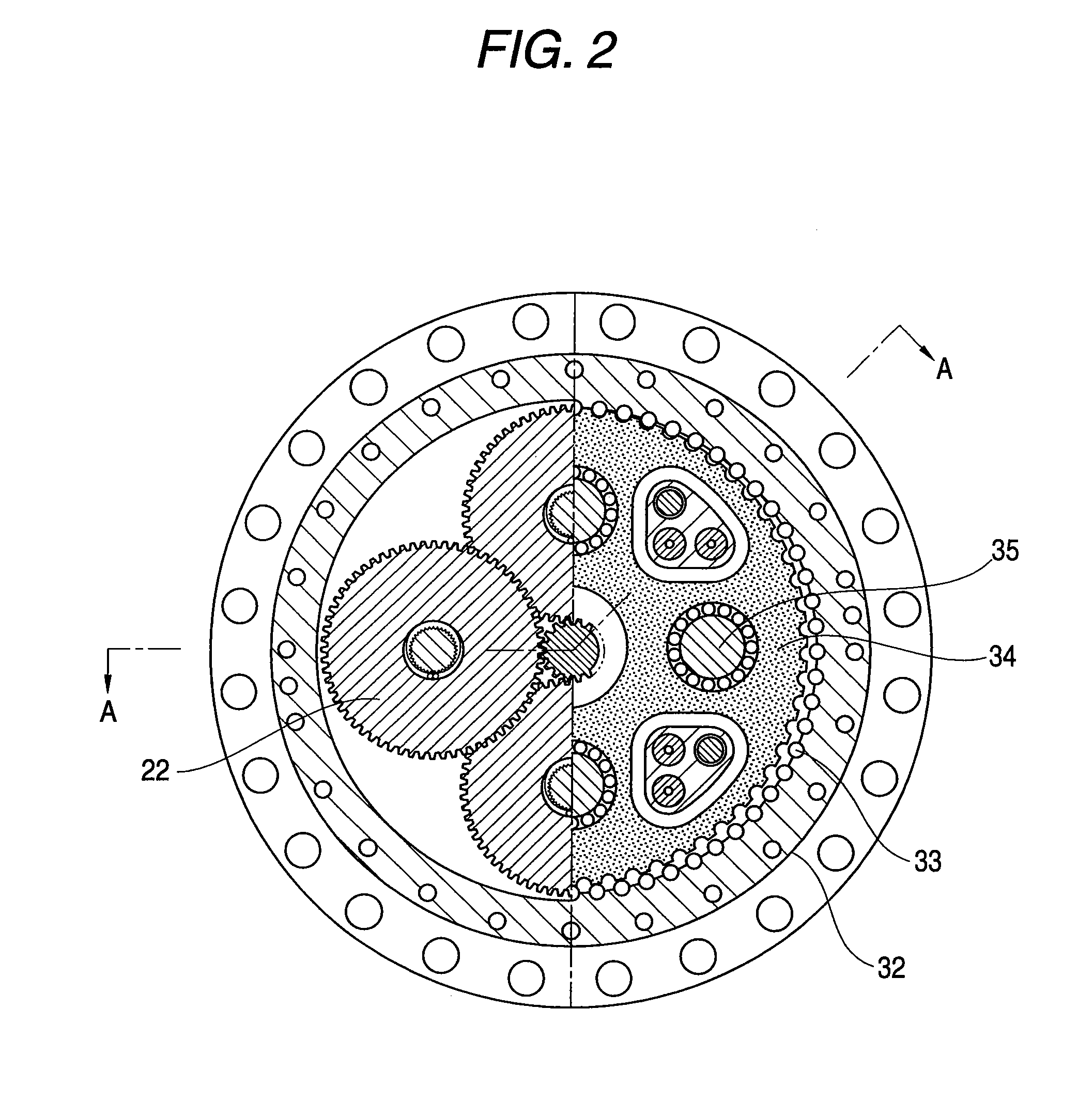
[0055]Hereinafter, a first embodiment of the present invention will be described with reference to FIGS. 1 and 2. FIG. 1 is a longitudinal cross-sectional view seen from the A-A direction of FIG. 2. FIG. 2 is a cross-sectional view taken along the line A-A of FIG. 1.

[0056]A reference numeral 100 indicates a yaw drive apparatus of a wind power generation apparatus. A reference numeral 200 indicates a speed reducer used in the yaw drive apparatus 100. The speed reducer 200 is constituted by a first stage speed reducing portion 10, a second stage speed reducing portion 20 connected to the first speed reducing portion 10, and a third stage speed reducing portion 30.

[0057]The first stage speed reducing portion 10 is constructed by a planetary speed reduction mechanism comprising an input sun gear 3 as an input part, which is fixedly connected to an output shaft 2 of a motor 1, a plurality of (three) planetary gears 4 engaged with the input sun gear 3 at the periphery of the input sun gea...

example 2

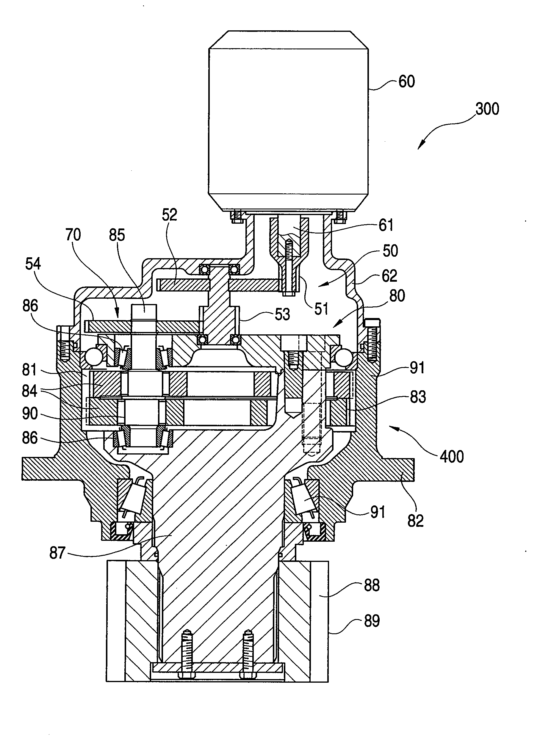
[0065]Next, a second embodiment of the invention will be described with reference to a longitudinal cross-sectional view shown in FIG. 3.

[0066]In FIG. 3, a reference numeral 300 indicates a yaw drive apparatus of a wind power generating apparatus. A reference numeral 400 indicates a speed reducer used in the yaw drive apparatus 300.

[0067]A first stage speed reducing portion 50 is constructed by a spur gear type speed reduction mechanism constituted by a first input spur gear 51 as an input part, which is fixedly connected to the output shaft 61 of the motor 60, and a first spur gear 52 engaged with the first input spur gear 51.

[0068]The reduction gear ratio of the first speed reducing portion 50 constructed by the spur gear type speed reduction mechanism is set to 1 / 6. The reduction gear ratio of the first stage speed reducing portion 50 is selectively selected from 1 / 2 to 1 / 12. A motor 60 is attached to the supporting member 62 of the motor.

[0069]A second stage speed reducing porti...

example 3

[0082]Next, a third embodiment related to the yaw drive method and apparatus using the above-described speed reducer will be described with reference to the attached drawings.

[0083]In FIGS. 5 and 6, a reference numeral 111 indicates a tower (column) of a wind power generation apparatus 112. A wind power generation unit 113 is capable of yawing and supported at the upper end of the tower 111 through a bearing 114, that is, it is supported to rotate in a substantially horizontal plane. Here, the wind power generation unit 113 has a well-known structure and is constituted by a nacelle housing 115, a rotor head (not shown) which is supported by the nacelle housing 115 and can rotate around a substantially horizontal axis, a plurality of windmill blades (not shown) of which a radial inner end is rotatably connected to the rotor head, and a motor (not shown) which is fixedly received in the nacelle housing 115 and generates a power using the rotation transferred from the rotor head.

[0084]...


PUM


Abstract

A yaw drive method of a wind power generation apparatus, in which a second gear engaged with a first gear attached to one of tower or a wind power generation unit supported to the upper end of the tower so as to be capable of yawing and supported to a tower or to the upper end of the tower is rotated by a drive motor attached to the other of the tower or the wind power generation unit for yawing the wind power generation unit. A drive energy, which is supplied to the drive motor for a predetermined time from when the supply of the drive energy to the drive motor begins to start, is made to be smaller than the drive energy supplied to the drive motor in a common yawing.

Description

CROSS-REFERENCE TO RELATED APPLICATIONS[0001]This application is a Divisional of U.S. patent application Ser. No. 10 / 567,613, filed Feb. 8, 2006, which is a Section 371 of International Application No. PCT / JP2004 / 011786, filed Aug. 11, 2004, which was published in Japanese language on Feb. 14, 2005, under International Publication No. WO 2005 / 015011 A1, the disclosure of which is incorporated herein by reference.BACKGROUND OF THE INVENTION[0002]The present invention relates to a speed reducer for use in a yaw drive apparatus which rotates a wind power generation unit of a wind power generation apparatus in a substantially horizontal plane, and a yaw drive method and an apparatus for wind power generation apparatus using the speed reducer.[0003]In general, the yaw drive apparatus of the wind power generation apparatus rotates a windmill power generation unit about a tower according to a wind in order that blades of the wind power generation apparatus can receive the wind, and rotates...

Claims


Application Information

Patent Timeline
Patent Type & Authority Applications(United States)
IPC IPC(8): F03D7/04F16H1/32H02P1/04F03D7/02
CPCF03D7/0204F05B2260/4031F05B2260/90F05B2270/1095Y02E10/723F05B2270/321F05B2270/329F16H1/32Y02E10/722F05B2270/32Y02E10/72
Inventor NOHARA, OSAMUYOKOYAMA, KATSUHIKOTANABE, SADAYUKI
Owner NABLESCO CORP
Why Eureka
Try Eureka