Atomic magnetometer and magnetic force measuring method

a magnetometer and magnetic force technology, applied in the field of magnetometers, can solve the problems of difficult removal of magnetic noise, low sensitivity to magnetic field detection, and difficulty in distinguishing the presence of magnetic noise from the output signal, and achieve the effect of high sensitivity to detect magnetic field

Active Publication Date: 2009-10-01
CANON KK
View PDF8 Cites 56 Cited by
  • Summary
  • Abstract
  • Description
  • Claims
  • Application Information

AI Technical Summary

Benefits of technology

[0024]According to the present invention, it is possible to detect the magnetic field with high sensitivity.

Problems solved by technology

For that reason, it is difficult to distinguish the presence of the magnetic noise from the output signal, so that it is very difficult to remove the magnetic noise.
For this reason, the conventional atomic magnetometers have been accompanied with a problem such that the sensitivity to magnetic field detection is lowered.
When the optical path of the pump beam and that of the probe beam are caused to accurately cross each other at right angles, the problem can be solved but it is very difficult to cross the optical paths of the pump beam and the probe beam with each other at right angles.

Method used


Image

  • Atomic magnetometer and magnetic force measuring method
  • Atomic magnetometer and magnetic force measuring method
  • Atomic magnetometer and magnetic force measuring method

Examples


first embodiment

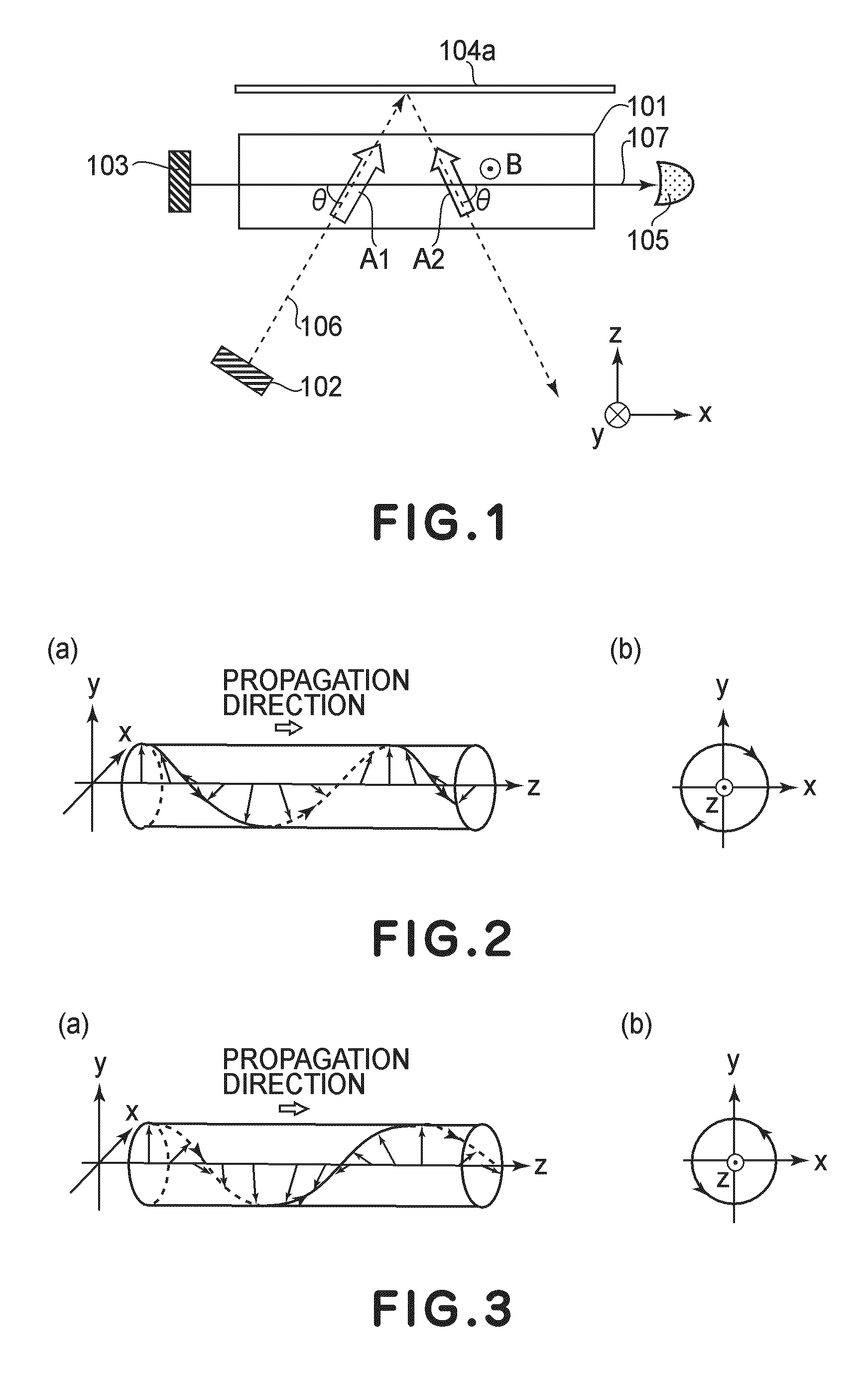
[0036]FIG. 1 is a schematic view showing an atomic magnetometer according to this embodiment.

[0037]The atomic magnetometer includes a cell 101 containing an atomic group (atoms), a light source for a pump beam (pump light source) 102, a light source for a probe beam (probe light source) 103, a first mirror 104a, and a detector 105.

[0038]The cell 101 is disposed between the pump light source 102 and the first mirror 104a and between the probe light source 103 and the detector 105. The first mirror 104a is placed in an optical path of the cell 101.

[0039]A pump beam 106 emitted from the pump light source 102 is circularly polarized light. The pump beam 106 passes through the cell 101 and is reflected by the first mirror 104a and then passes through the cell 101 again. In FIG. 1, an incident angle of the pump beam 106 with respect to the first mirror 104a is indicated as a large angle but actually the incident angle is small, so that an optical path of incident light and an optical path...

embodiment 1

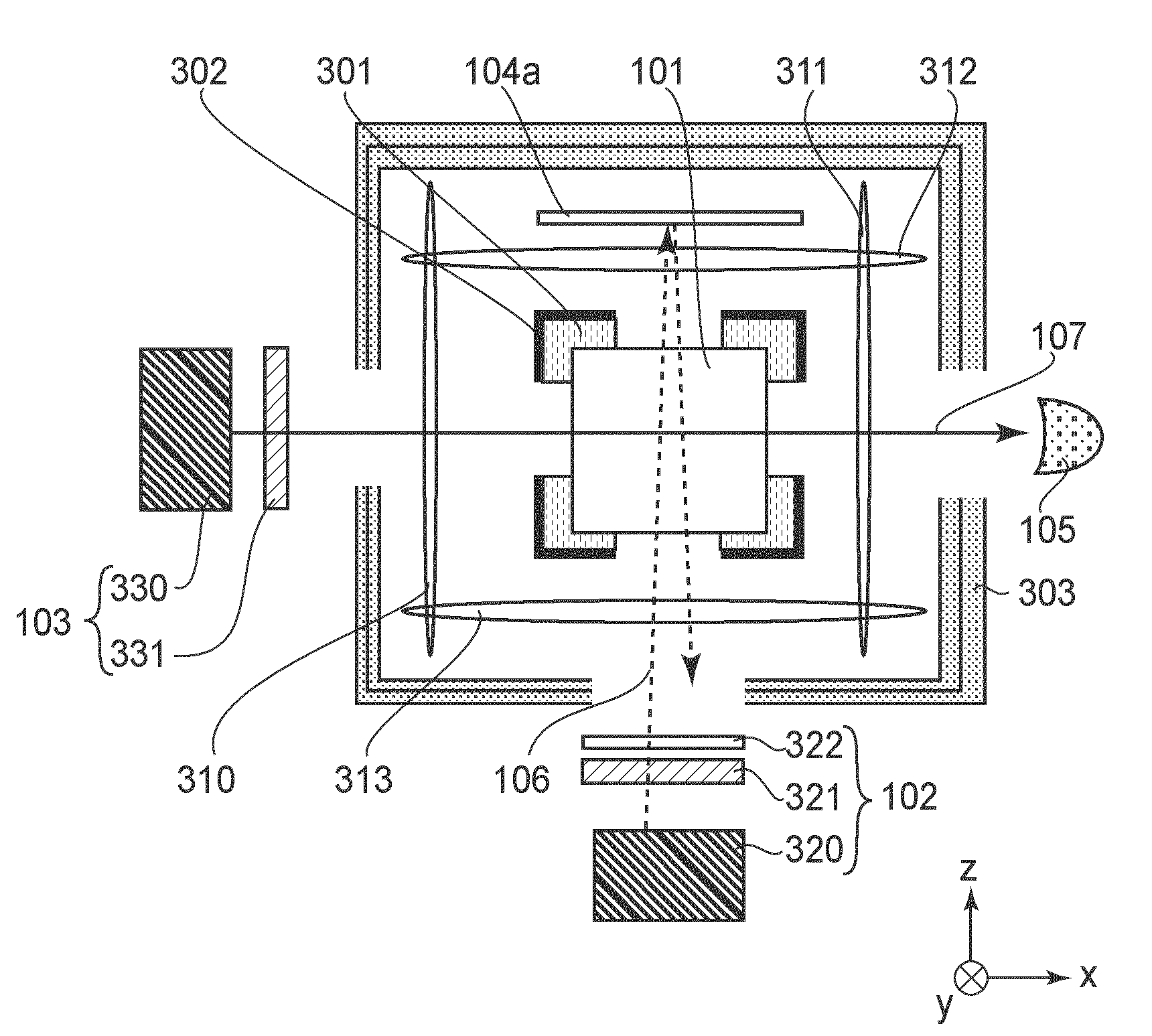
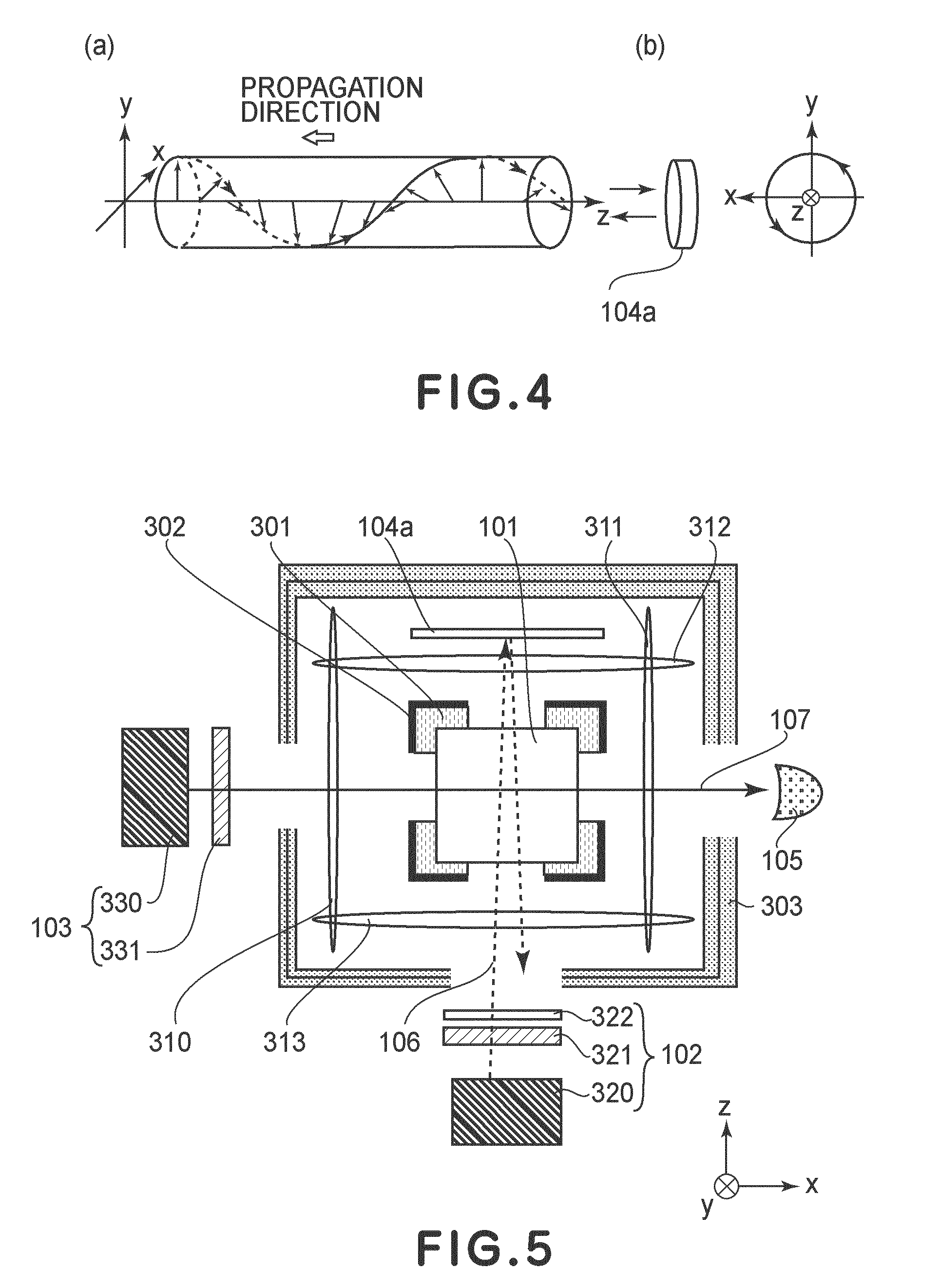
[0116]FIG. 5 is a schematic sectional view for illustrating an optical pumping magnetometer (atomic magnetometer) according to this embodiment.

[0117]The atomic magnetometer of this embodiment includes the cell 101 containing the atomic group, the pump light source 102, the probe light source 103, the first mirror 104a, and the detector 105.

[0118]The cell 101 is disposed between the pump light source 102 and the first mirror 104a and between the probe light source 103 and the detector 105. The optical path of the probe beam 107 crosses the optical path of the pump beam 106 in the cell 101.

[0119]The pump beam 106 emitted from the pump light source 102 is the circularly polarized light. The pump beam 106 passes through the cell 101 and is reflected by the first mirror 104a and thereafter passes through the cell 101 again.

[0120]The probe beam 107 emitted from the probe light source 103 is the linearly polarized light. The probe beam 107 propagates in a direction (x-direction in FIG. 5) ...

embodiment 2

[0164]FIG. 9 is a schematic sectional view for illustrating an optical atomic magnetometer according to this embodiment.

[0165]The atomic magnetometer of this embodiment includes the cell 101 containing the atomic group, the pump light source 102, the probe light source 103, and the detector 105. The atomic magnetometer further includes the first mirror 104a and a second mirror 104b.

[0166]The cell 101 is disposed between the pump light source 102 and the first mirror 104a and between the probe light source 103 and the detector 105.

[0167]The second mirror 104b is disposed between the cell 101 and the pump light source 102. Specifically, the second mirror 104b is disposed somewhat rightwardly in FIG. 9 so as not to overlap an optical axis of the pump light source 102.

[0168]The first mirror 104a and the second mirror 104b are provided in parallel to each other. The cell 101 is provided between the first mirror 104a and the second mirror 104b. As the first mirror 104a and the second mir...


PUM


Abstract

An atomic magnetometer includes a cell containing an atomic group, a pump light source, a probe light source, a mirror, and a detector. The cell is disposed between the pump light source and the mirror and between the probe light source and the detector. A pump beam emitted from the pump light source is circularly polarized light. The pump beam passes through the cell and is reflected by the mirror and then passes through the cell again. The probe beam emitted from the probe light source is linearly polarized light. An optical path of the probe beam is parallel to a plane of incidence of the pump beam and is also parallel to a surface of the mirror. The optical path of the probe beam crosses an optical path of the pump beam in the cell. The probe beam which has passed through the cell enters the detector.

Description

FIELD OF THE INVENTION AND RELATED ART[0001]The present invention relates to a magnetometer for measuring magnetic field strength or magnetic field gradient, specifically an atomic magnetometer utilizing paramagnetic Faraday effect.[0002]In recent years, high-sensitivity atomic magnetometers capable of measuring a magnetic field smaller than that of a superconducting quantum interface device (SQUID) by utilizing atomic spin have been proposed (U.S. Pat. No. 7,038,450 and J. C. Allred, et. al., “High-Sensitivity Atomic Magnetometer Unaffected by Spin-Exchange Relaxation”, Physical Review Letters, Vol. 89, No. 13, p. 130801, September 2002).[0003]These atomic magnetometers include a cell containing alkali metal gas, a light source for a pump beam (pump light source), and a light source for a probe beam (probe light source).[0004]These atomic magnetometers are operated in the following manner. First, alkali metal gas in the cell is spin-located by a circularly polarized pump beam. When...

Claims


Application Information

Patent Timeline
Patent Type & Authority Applications(United States)
IPC IPC(8): G01V3/00
CPCG01R33/0385B82Y25/00G01R33/26
Inventor ICHIHARA, SUNAOMIZUTANI, NATSUHIKOSUGIOKA, HIDEYUKIKOBAYASHI, TETSUOISHIKAWA, KIYOSHITAUE, SHUJI
Owner CANON KK
Why Eureka
Try Eureka