Semi-Digital Delay Locked Loop Circuit and Method

Active Publication Date: 2009-10-01
XUESHAN TECH INC
View PDF14 Cites 54 Cited by
  • Summary
  • Abstract
  • Description
  • Claims
  • Application Information

AI Technical Summary

Benefits of technology

[0007]The present invention relates to a semi-digital DLL (delay locked loop) circuit whose locking precision is tunable. Such a circuit is advantageous in systems where DLL jitt

Problems solved by technology

High-speed circuits may also require clocks with programmable duty cycle and delay.
Note that any of the passive techniques for reducing clock skew wi

Method used


Image

  • Semi-Digital Delay Locked Loop Circuit and Method
  • Semi-Digital Delay Locked Loop Circuit and Method
  • Semi-Digital Delay Locked Loop Circuit and Method

Examples


Embodiment Construction

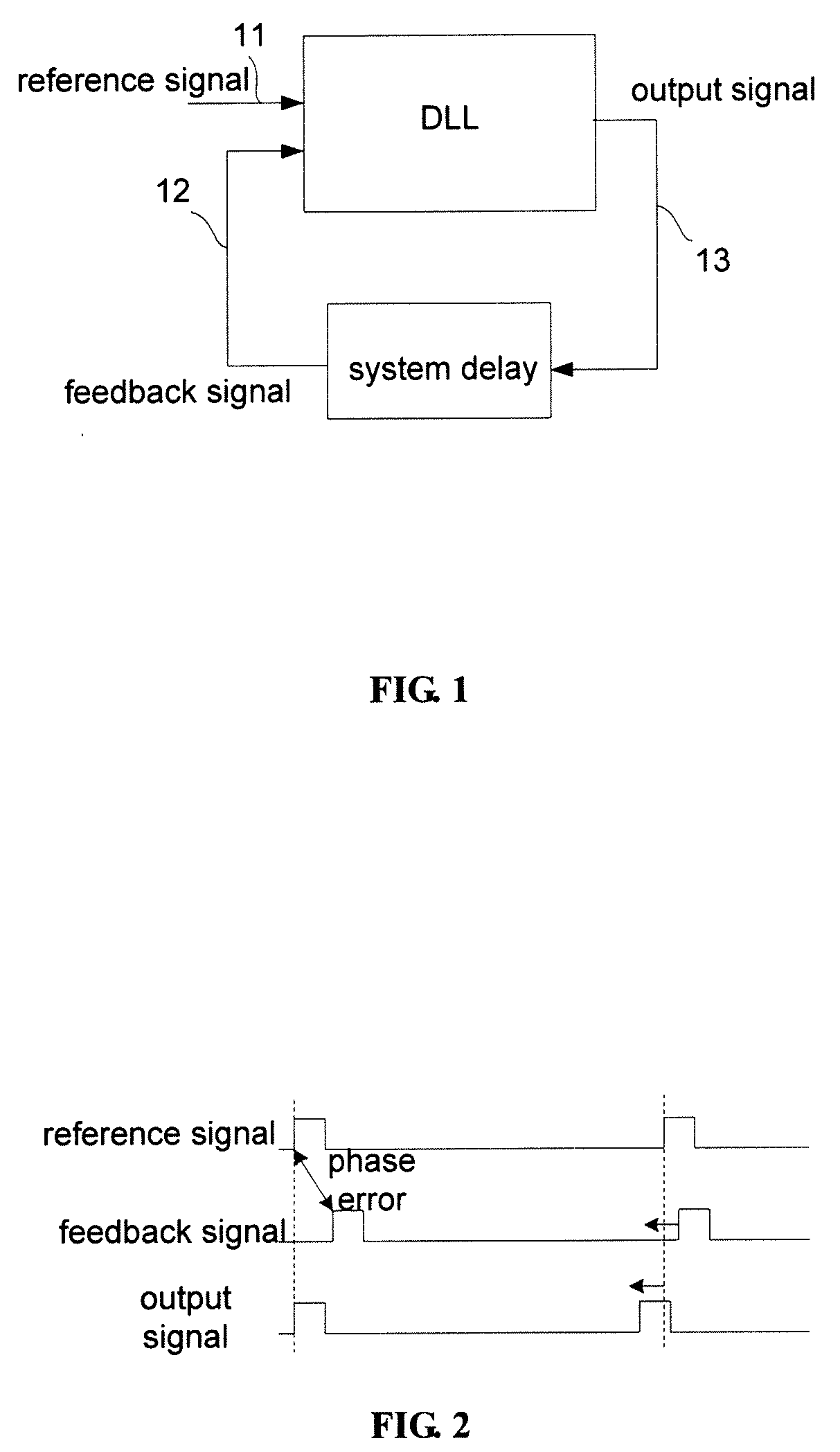
[0018]A view of a DLL in a system is shown in FIG. 1. A reference signal 11 is generated internally. For example in a video system, this reference signal 11 is obtained by processing the horizontal synchronization signal (HSYNC). An output signal 13 of the DLL triggers some activities on the system board and after some delays returns a feedback signal 12 to the DLL. The objective of the DLL is to adjust the phase of the output signal 13 such that feedback signal 12 is aligned or be at a fixed offset from reference signal 11. FIG. 2 shows the relationship among the three signals.

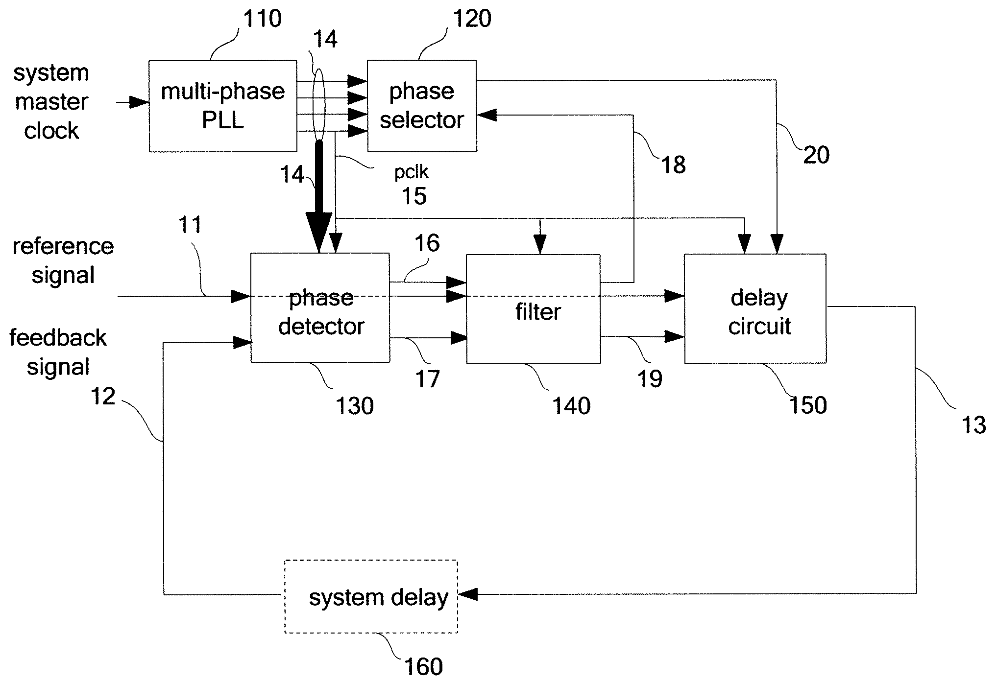
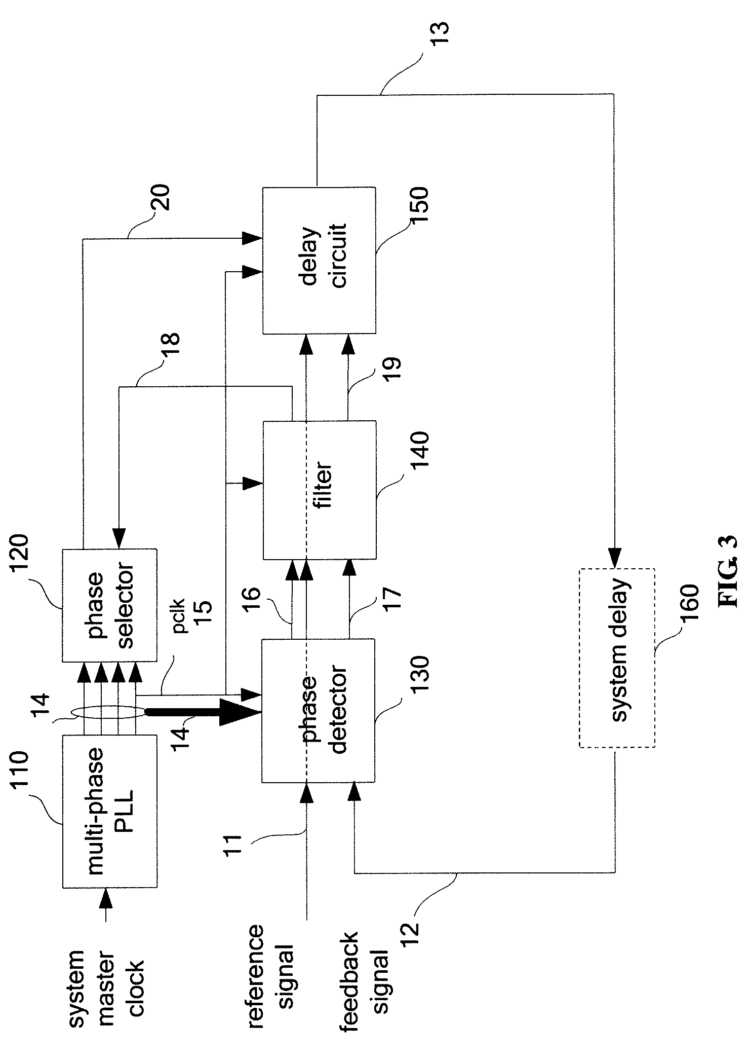
[0019]The DLL architecture in the invention, with reference to FIG. 3 showing a block diagram, includes a multi-phase PLL 110, a phase selector 120, a phase detector 130, a filter 140 and a delay circuit 150. The multi-phase PLL 110 generates a set of clocks 14 by subdividing one clock period of a system master clock into evenly-spaced phases. The PLL frequency is programmable. The DLL jitter is inversely pro...


PUM


Abstract

A scalable DLL (delay locked loop) circuit that has a calibration mechanism to auto tune locking precision. The delay locked loop circuit includes a multi-phase phase locked loop circuit for generating a plurality of phase signals according to a system clock, wherein one of the phase signals is a pixel clock; a phase detector for detecting an integral phase error and a fractional phase error between a reference signal and a feedback signal according to the pixel clock; a phase selector for selecting one of the phase signals according to the fractional phase error; and a delay circuit for shifting the phase of the reference signal according to the integral phase error and the selected phase signal to generate an output signal.

Description

CROSS REFERENCE TO RELATED PATENT APPLICATION[0001]This application claims the benefit of U.S. provisional patent application No. 61 / 039,440 filed on Mar. 26, 2008.FIELD OF THE INVENTION[0002]The present invention relates to a scalable DLL (delay locked loop) circuit for tuning locking precision.BACKGROUND OF THE INVENTION[0003]Synchronous sequential systems rely on globally synchronized clocks. With the increase in clock rates, low-skew clock distributions are becoming increasingly critical to achieving design speed objectives. High-speed circuits may also require clocks with programmable duty cycle and delay. For all these applications, comprehensive clock management is necessarily implemented on a chip. The Phase- and Delay-Locked Loops are used to achieve low clock skew distributions. The principles of frequency synthesis, by which the clock rates can be multiplied and divided, are outlined, together with its applications. The basic idea of the active closed-loop clock skew comp...

Claims


Application Information

Patent Timeline
IPC IPC(8): H03L7/06H03L7/00H03H11/16
CPCH03L7/07H04N5/126H03L7/0996H03L7/0814
Inventor SMITH, STERLINGYEH, ELLEN CHENLU, WEN CAI
Owner XUESHAN TECH INC
Why Eureka
Try Eureka