Method of manufacturing piezoelectric actuator, and liquid ejection head

Active Publication Date: 2009-10-01
FUJIFILM CORP
View PDF1 Cites 15 Cited by
  • Summary
  • Abstract
  • Description
  • Claims
  • Application Information

AI Technical Summary

Benefits of technology

[0022]According to the present invention, by increasing the film thickness of the wire portions that supply electricity to the piezoelectric element through the upper electrode film and the lower electrode film, it is possible to reduce the electrical resistan

Problems solved by technology

For example, the stress applied to the piezoelectric film by the substrate or the interposed layer gives rises to cracking in the piezoelectric film, affects the so-called piezoelectric constant, and also affects the long-term reliability of the piezoelectric film.
However, if a lower electrode (common electrode) and a piezoelectric film are formed on a substrate of insulating material (e.g., silicon (Si)), then it is difficult to reduce the electrical resistance of the lower electrode.
In Japanese Patent Application Publication No. 2001-113712, a diaphragm is deposited as a film and bonded to a pressure chamber component; however, if a diaphragm of several micrometers (em) or greater is deposited, then it is difficult to control the stre

Method used


Image

  • Method of manufacturing piezoelectric actuator, and liquid ejection head
  • Method of manufacturing piezoelectric actuator, and liquid ejection head
  • Method of manufacturing piezoelectric actuator, and liquid ejection head

Examples


Example

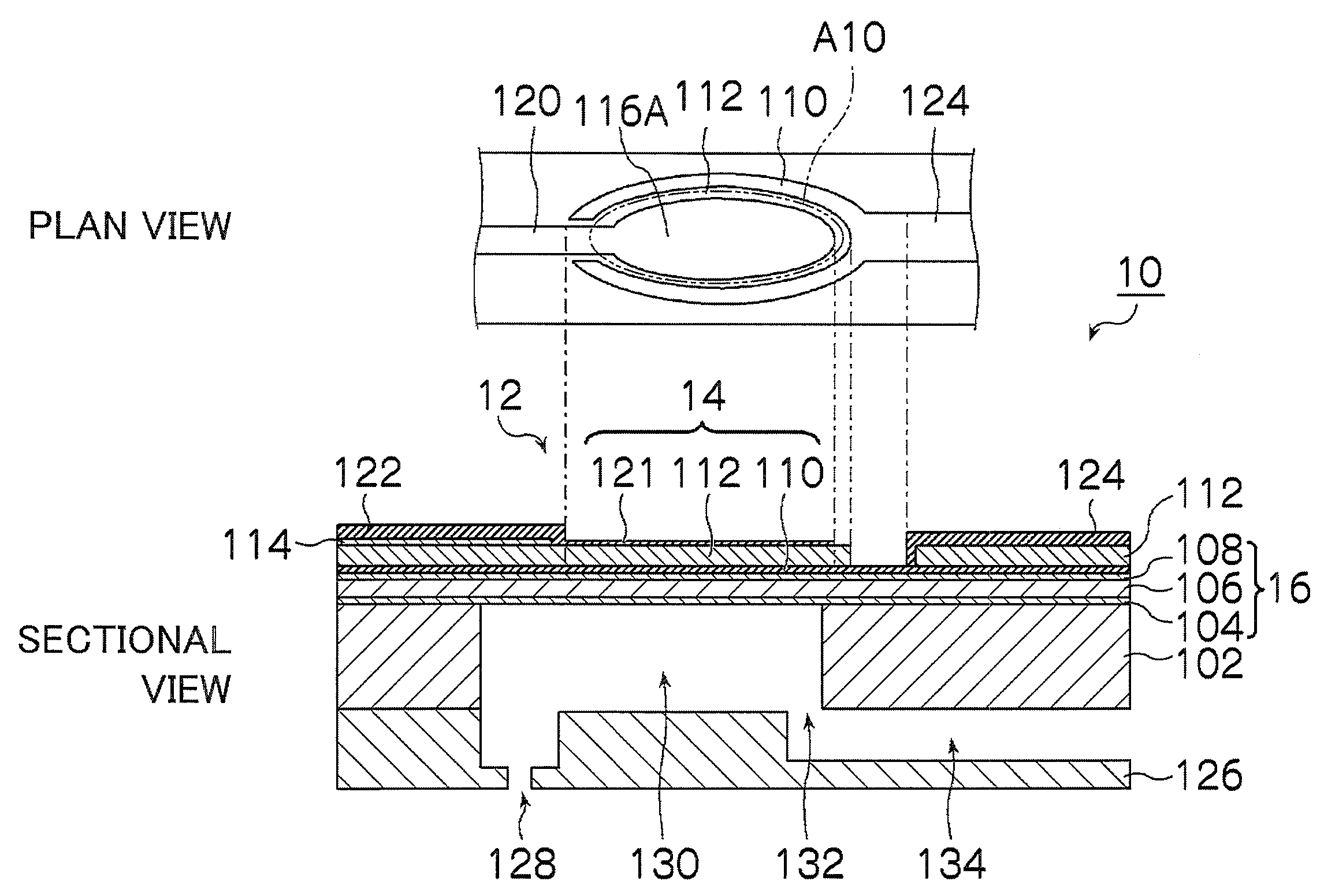
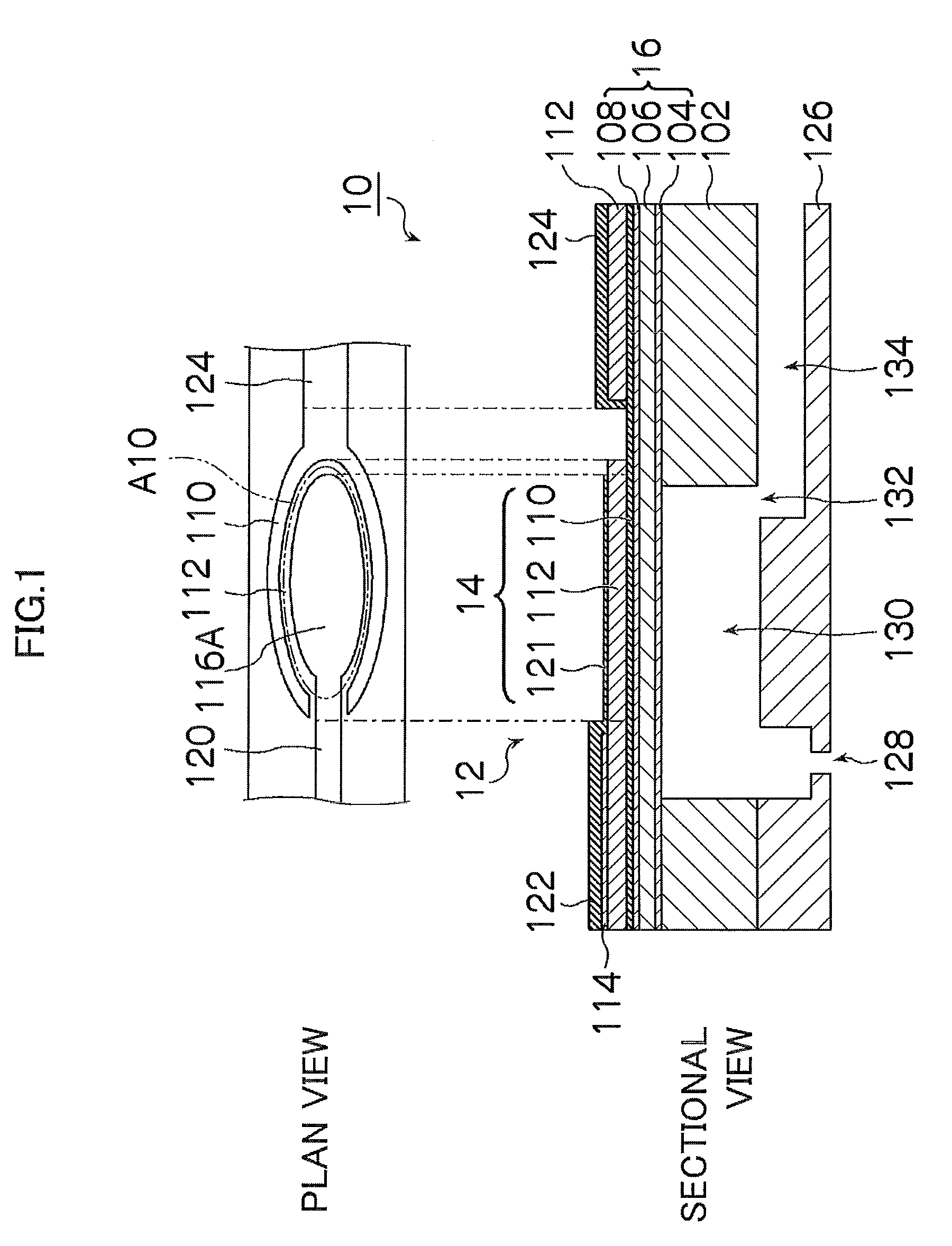
[0032]FIG. 1 is a diagram showing a plan view and a cross-sectional view of a liquid ejection head according to a first embodiment of the present invention.

[0033]As shown in FIG. 1, the liquid ejection head 10 (hereinafter also referred to as a “recording head”) according to the present embodiment includes: a nozzle 128, which forms an ink ejection port; a pressure chamber 130, which is connected to the nozzle 128; and a piezoelectric actuator 12, which alters the internal volume of the pressure chamber 130.

[0034]Although not shown in FIG. 1, there are a plurality of the nozzles 128 arranged in a two-dimensional arrangement (matrix configuration) in the ejection face (nozzle surface) of the recording head 10. The pressure chambers 130 corresponding respectively to the nozzles 128 are arranged inside the recording head 10, and each nozzle 128 is connected to the corresponding pressure chamber 130. Ink supply ports 132 are formed respectively at ends of the pressure chambers 130 (the ...

Example

Second Embodiment

[0062]Next, a second embodiment of the present invention is described.

[0063]FIG. 3 is a diagram showing a plan view and a cross-sectional view of a liquid ejection head according to the second embodiment of the present invention.

[0064]As shown in FIG. 3, the piezoelectric actuator 12 according to the present embodiment has a structure in which the lower electrode film 110 is a common electrode and the upper electrode film 121 is an individual electrode (i.e., an upper address structure). The upper electrode film 121 is connected to an upper wire 144. The upper wire 144 is connected to an external wire (e.g., a flexible cable) (not shown). On the other hand, the lower electrode film 110 corresponding to the respective pressure chambers 130 is connected to lower wires 146, which are formed on a groove portion 112A of the piezoelectric film 112. The lower wires 146 are connected electrically to each other at a position that is not illustrated, and are earthed. The uppe...


PUM

PropertyMeasurementUnit
Thicknessaaaaaaaaaa
Piezoelectricityaaaaaaaaaa

Abstract

The method of manufacturing a piezoelectric actuator, includes the steps of: forming a lower electrode film on an insulating substrate; forming a piezoelectric film on the lower electrode film; forming a slit on the piezoelectric film to expose a portion of the lower electrode film on an upper surface side of the piezoelectric film; forming an insulating layer which covers a portion of the piezoelectric film; forming an upper electrode film so as to span the insulating layer and the piezoelectric film; forming, on the piezoelectric film, a lower wire in connection with the portion of the lower electrode film exposed through the slit; depositing a first metal film on the lower wire and thereby making a film thickness of the lower wire greater than a film thickness of the lower electrode film; and depositing a second metal film on a portion of the upper electrode film on the insulating layer and thereby making a film thickness of the portion of the upper electrode film on the insulating layer greater than a film thickness of a portion of the upper electrode film that has been deposited directly on the piezoelectric film.

Description

BACKGROUND OF THE INVENTION[0001]1. Field of the Invention[0002]The present invention relates to a method of manufacturing a piezoelectric actuator and a liquid ejection head, and more particularly to a method of manufacturing a piezoelectric actuator in which a piezoelectric film is arranged between two electrode films, and a liquid ejection head comprising this piezoelectric actuator.[0003]2. Description of the Related Art[0004]Japanese Patent Application Publication No. 2001-113712 discloses a method of manufacturing an inkjet head in which films of an electrode member, a piezoelectric member and a diaphragm member are deposited onto each of a plurality of substrates, and the diaphragm member on the plurality of substrates after the film deposition is bonded with a pressure chamber component having a surface area that is broader than the combined surface area of the plurality of substrates.[0005]Japanese Patent Application Publication No. 2002-217468 discloses a method of manufac...

Claims


Application Information

Patent Timeline
IPC IPC(8): B41J2/045H01L41/22B41J2/055H01L41/09B41J2/135B41J2/14B41J2/145B41J2/16H01L41/18H01L41/29H01L41/39
CPCB41J2/14233B41J2/161B41J2/1628B41J2/1629B41J2/1642B41J2/1643Y10T29/49155B41J2002/14266B41J2002/14411B41J2202/21H01L41/0973H01L41/319Y10T29/42B41J2/1646H10N30/2047H10N30/079
Inventor MITA, TSUYOSHI
Owner FUJIFILM CORP
Why Eureka
Try Eureka