Systems and methods for speckle reduction

a technology of speckle reduction and speckle, applied in the field of systems and methods for reducing speckle, can solve the problems of serious degradation of image quality, and granular intensity pattern known as speckl

Active Publication Date: 2009-10-01
CORNING INC
View PDF17 Cites 18 Cited by
  • Summary
  • Abstract
  • Description
  • Claims
  • Application Information

AI Technical Summary

Benefits of technology

[0005]According to one embodiment, a laser projection system including a system controller, a visible light source, and a light disrupting element is provided. The laser projection system is programmed to generate at least a portion of a scanned laser image by operating the laser for optical emission of encoded image data and controlling a scanning element to scan an optical signal of the visible light source across a plurality of image pixels. The scanned optical signal comprises a low spatial frequency beam and a high spatial frequency beam, such that the low spatial frequency beam generates a low spatial frequency image having spatial frequencies below a spatial frequency threshold, the high spatial frequency beam generates a high spatial frequency image having spatial frequencies that are above the spatial frequency threshold. The scanned laser image is a sum of the high spatial frequency image and the low spatial frequency image The laser project system is programmed to alter the low spatial frequency beam by directing and focusing the low spatial frequency beam upon an out of focus light disrupting element, wherein the light disrupting element is out of focus with respect to an intermediate image that is formed by scanning and focusing the low spatial frequency beam.

Problems solved by technology

Speckle that is present in the image may seriously degrade the image quality.
Speckle may result whenever a coherent light source is used to illuminate a rough surface, for example, a screen, or any other object that produces a diffused reflection or transmission.
At an observation point, for example in the observer's eye or at the sensor of a camera, these beams may interfere constructively to form a bright spot, or destructively to form a dark spot, producing a random granular intensity pattern known as speckle.
For example, if an image is formed on the screen using laser beams, such granular structure will represent noise, or a serious degradation of the image quality.
By moving the small size diffuser, the phase of the electric field is scrambled over time, which results in changing the perceived speckle pattern.
However, it is much more difficult to incorporate a diffuser to reduce the perceived speckle in a laser scanning projector system because the scanned spot is moving extremely fast and stays at approximately the same location over durations in the order of 40 nS.
It is very difficult to display multiple speckle patterns over such a small duration because the maximum speed at which different speckle patterns can be displayed is the frequency at which full frames are being displayed.

Method used


Image

  • Systems and methods for speckle reduction
  • Systems and methods for speckle reduction
  • Systems and methods for speckle reduction

Examples


Embodiment Construction

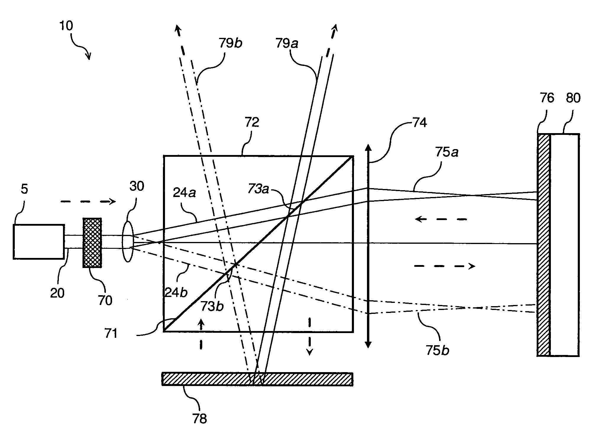
[0014]Generally, the present inventors have recognized that placing a light disrupting element within the path of a laser that is being scanned onto a projection surface aid in eliminating speckle that is visible to a human eye or detector. More specifically, embodiments of the present invention utilize the concept of a diffusing surface but, instead of moving the diffuser extremely fast, the embodiments take advantage of the fact that, in a laser scanning projection system, the spot is moving extremely fast. To fully understand the operations of the particular embodiments, it may be helpful to review technical information regarding scanned laser sources and light disrupting surfaces, and their relationship to speckle in a scanned laser image.

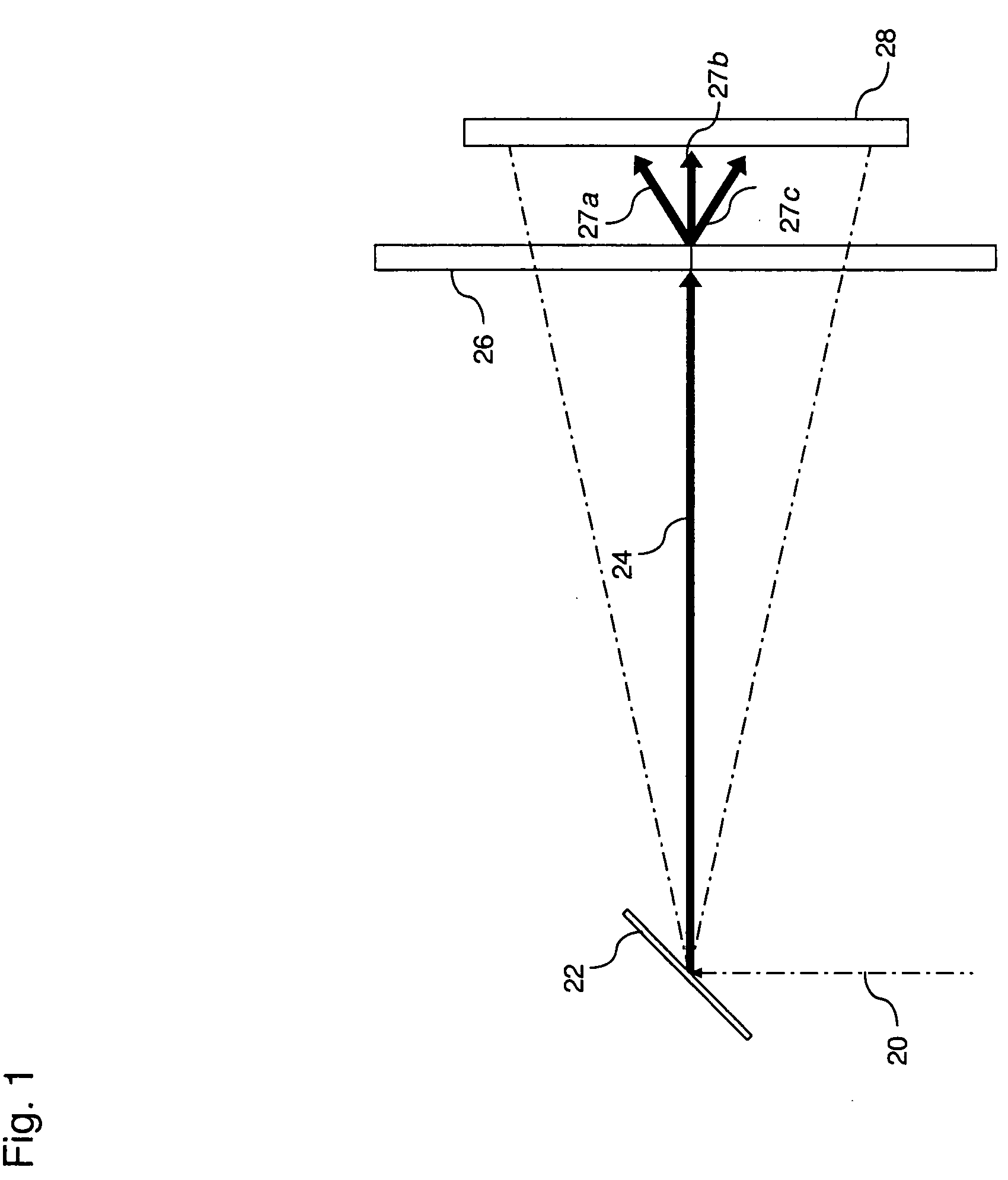
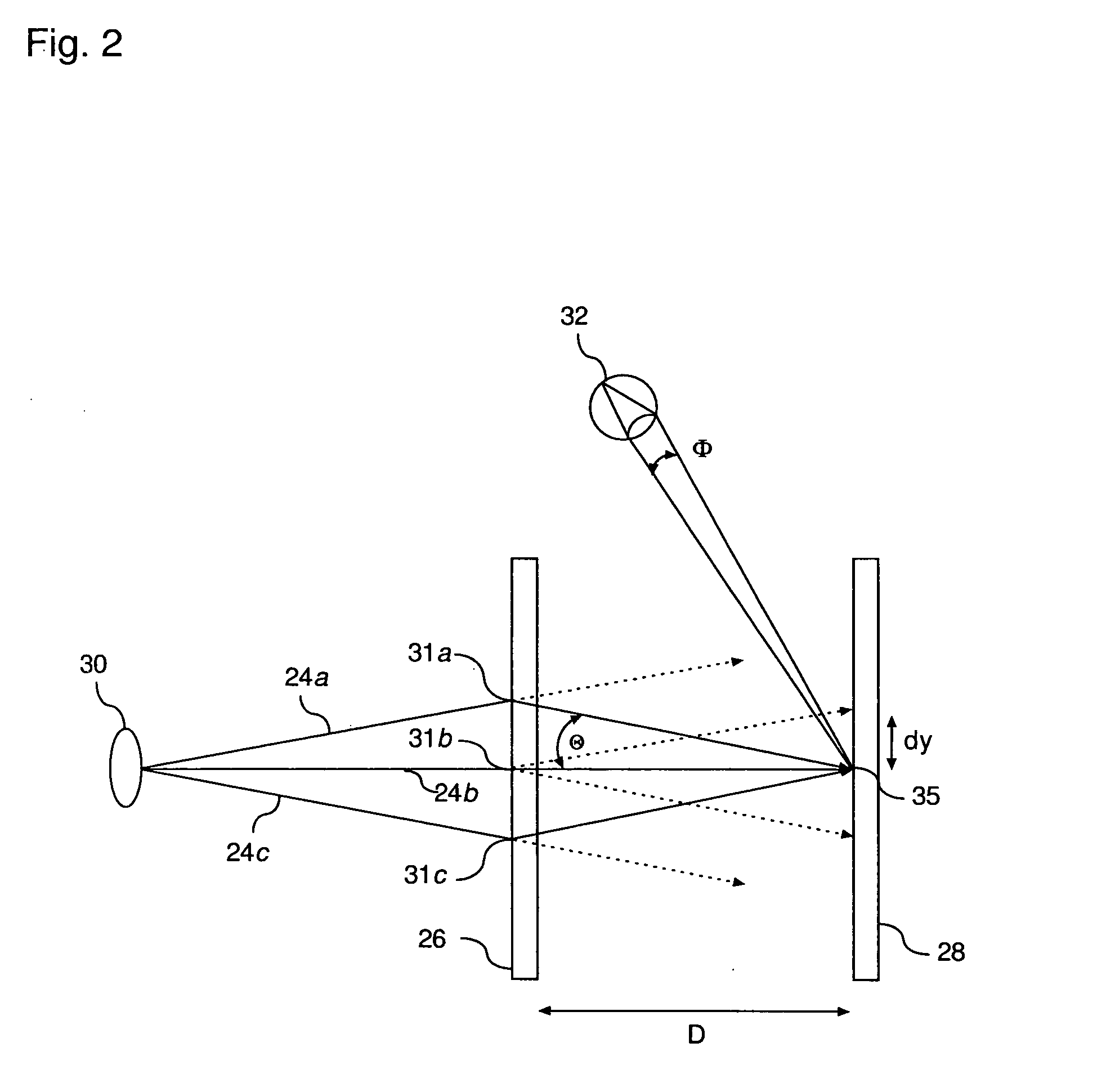
[0015]For illustrative purposes, the general concept of using an out of focus diffusing or diffracting surface in a laser scanning projection system 10 is illustrated in FIG. 1. In the particular illustration, an optical signal 20, which may be...


PUM

PropertyMeasurementUnit
spatial frequencyaaaaaaaaaa
spatial frequenciesaaaaaaaaaa
wavelengthsaaaaaaaaaa

Abstract

A laser projection system including a system controller, a visible light source, and a light disrupting element is provided. The visible light source includes at least one laser and the laser projection system is programmed to scan a scanned optical signal of the visible light source across a plurality of image pixels. The scanned optical signal comprises a low spatial frequency beam and a high spatial frequency beam, and the low spatial frequency beam generates a low spatial frequency image having spatial frequencies below a spatial frequency threshold, the high spatial frequency beam generates a high spatial frequency image having spatial frequencies that are above the spatial frequency threshold, and the scanned laser image is a sum of the high spatial frequency image and the low spatial frequency image. The low spatial frequency beam is altered by an out of focus light disrupting element.

Description

BACKGROUND OF THE INVENTION[0001]The present invention relates to systems and methods for reducing speckle in a scanned image. More specifically, the present invention relates to the design and methods of operation of a visible light source and laser projection system to reduce the presence of speckle that may be visible in a laser projection image. Speckle that is present in the image may seriously degrade the image quality. Speckle may result whenever a coherent light source is used to illuminate a rough surface, for example, a screen, or any other object that produces a diffused reflection or transmission.[0002]Particularly, a multitude of small areas of the screen or other reflecting object scatter light into a multitude of reflected beams with different points of origination and different propagation directions. At an observation point, for example in the observer's eye or at the sensor of a camera, these beams may interfere constructively to form a bright spot, or destructivel...

Claims


Application Information

Patent Timeline
Patent Type & Authority Applications(United States)
IPC IPC(8): G02F1/23G02B26/08G02B27/42G02B5/02G02B5/08
CPCG02B27/48G02B13/22
Inventor GOLLIER, JACQUES
Owner CORNING INC
Why Eureka
Try Eureka