E-paper apparatus and driving substrate thereof

a technology of e-paper and driving substrate, which is applied in the direction of printed circuits, instruments, optics, etc., can solve the problems of increasing the capacitive load of the e-paper apparatus b>4/b>, the size and weight of the conventional flat panel display apparatus are not more advantageous, and the apparatus cannot be used, so as to reduce the capacitive load of the data line and reduce the power consumption of the e-paper apparatus and the driving substrate thereo

Inactive Publication Date: 2009-10-01
AUSK OPTOELECTRONICS
View PDF3 Cites 12 Cited by
  • Summary
  • Abstract
  • Description
  • Claims
  • Application Information

AI Technical Summary

Benefits of technology

[0016]As mentioned above, in the e-paper apparatus and the driving substrate thereof according to the present invention, the common line is substantially disposed parallel to the data line and is disposed crossingly with the scan line. The second scan line may be used as a storage electrode, such that the capacitive load of the data line can be decreased so as to reduce the power consumption of the e-paper apparatus and the driving substrate thereof.

Problems solved by technology

However, the size and weight of the conventional flat panel display apparatus are not more advantageous compared to the paper prints that are easy to read and carry.
Moreover, as the battery power of the flat panel display apparatus is used up without connecting to an external power source, the apparatus cannot be used.
A coupling capacitor is formed with the crossing disposition of the data line 424 and the common line 422, and this leads to the increase in capacitive load of the e-paper apparatus 4 as well as the power consumption.

Method used


Image

  • E-paper apparatus and driving substrate thereof
  • E-paper apparatus and driving substrate thereof
  • E-paper apparatus and driving substrate thereof

Examples


first embodiment

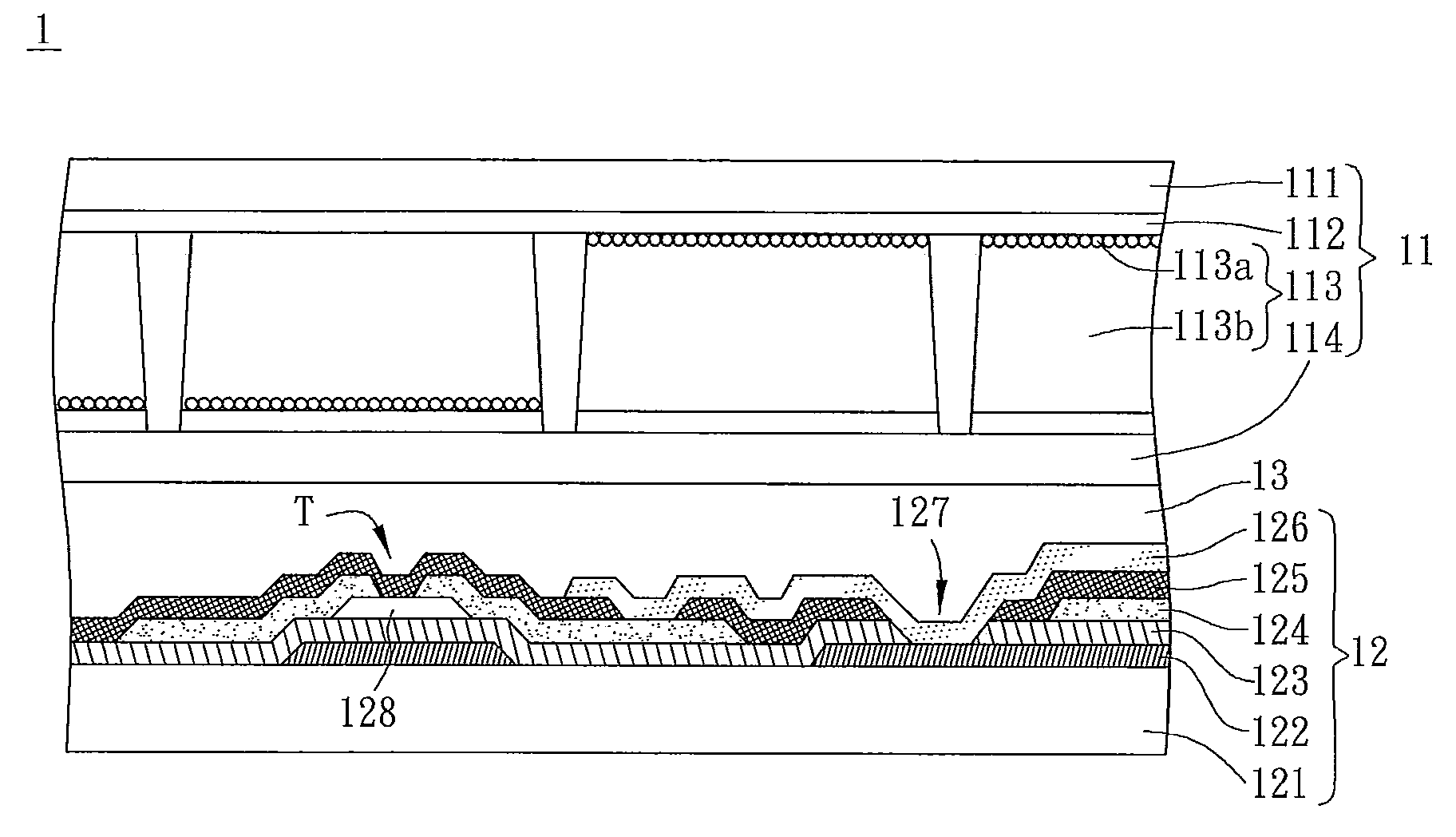
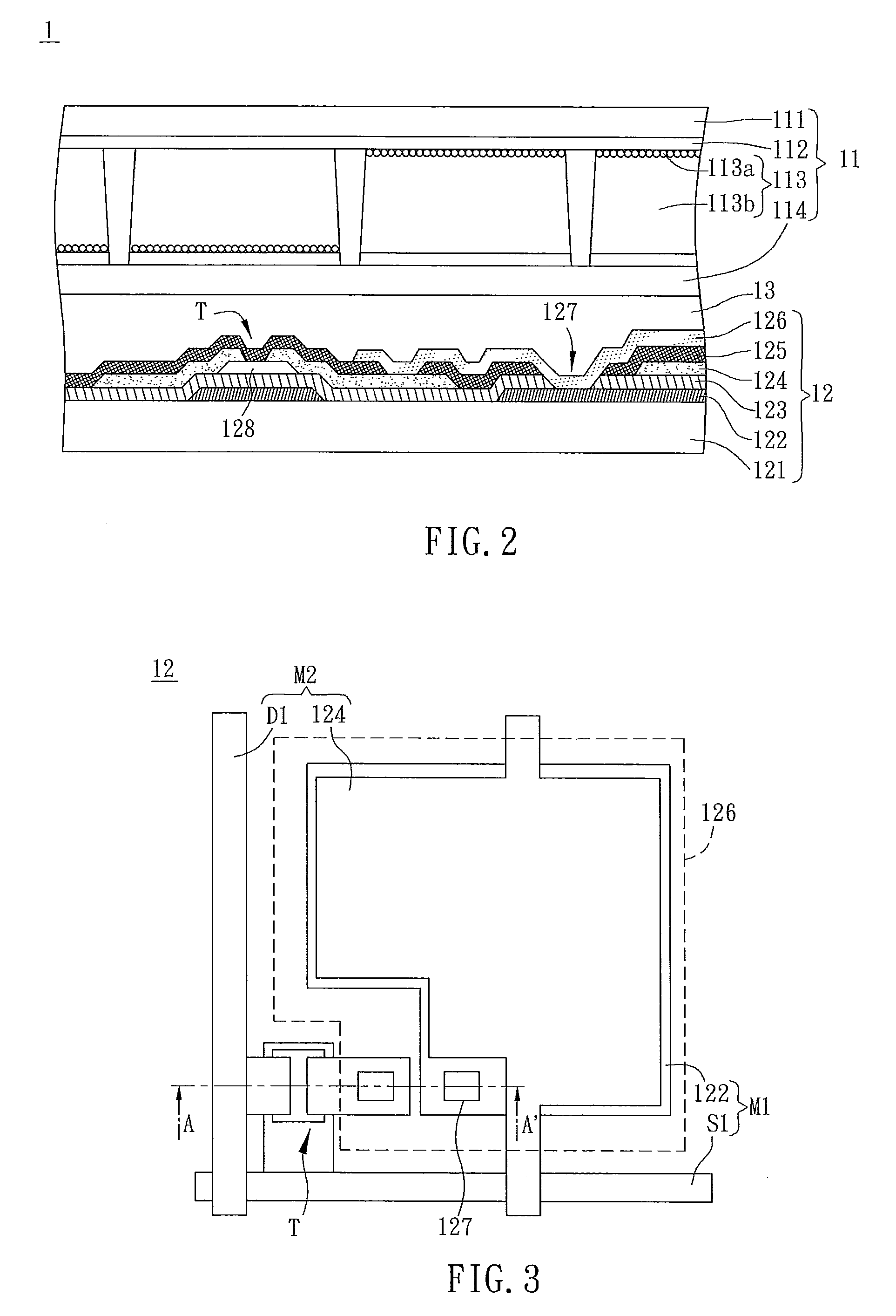
[0026]FIG. 2 is a cross-sectional view of an e-paper apparatus 1 according to the first embodiment of the present invention. With reference to FIG. 2, the e-paper apparatus 1 includes an e-paper body 11 and a driving substrate 12, which may be connected to the e-paper body 11 through an adhesive layer 13.

[0027]The e-paper body 11 includes an upper substrate 111, a transparent electrode layer 112, an electrophoretic material 113 and a lower substrate 114. The transparent electrode layer 112 is disposed opposite to the driving substrate 12 and the upper substrate 111 is disposed on a side of the transparent electrode layer 112. In practice, the material of the transparent electrode layer 112 may be indium tin oxide (ITO), aluminum zinc oxide (AZO), indium zinc oxide (IZO), or cadmium tin oxide.

[0028]The electrophoretic material 113 is disposed between the transparent electrode layer 112 and the lower substrate 114, and includes a plurality of charged particles 113a and a dielectric so...

second embodiment

[0041]FIG. 6 is a cross-sectional view of the e-paper apparatus 2 according to the second embodiment of the present invention. The e-paper apparatus 2 includes an e-paper body 21 and a driving substrate 22. The e-paper body 21 is connected to the driving substrate 22 by an adhesive layer 23. The technical features and functions of the e-paper body 21 and adhesive layer 23 are the same as the e-paper body 11 and adhesive layer 13 of the first embodiment, so a detailed description is omitted herein. The driving substrate 22 is illustrated as follows.

[0042]FIG. 7 is a top view of one of the pixels on the driving substrate 22 of the e-paper apparatus 2 according to the second embodiment, and the cross section of the driving substrate 22 in FIG. 6 is the cross section along a line C-C′ in FIG. 7. With reference to FIGS. 6 and 7, the driving substrate 22 has a first metal layer M1′, a second metal layer M2′, and a pixel electrode 226.

[0043]The first metal layer M1′ has a first scan line S...


PUM

PropertyMeasurementUnit
storage capacitanceaaaaaaaaaa
areasaaaaaaaaaa
areaaaaaaaaaaa

Abstract

A driving substrate of an e-paper apparatus includes a first metal layer, a second metal layer and a pixel electrode. The first metal layer has a scan line and a first storage electrode. The second metal layer has a data line and a common line. The scan line and the data line are disposed crossingly. The common line is disposed parallel to the data line substantially. The common line and the scan line are disposed crossingly. The pixel electrode is disposed over the common line and is electrically connected to the first storage electrode through a via.

Description

CROSS REFERENCE TO RELATED APPLICATIONS[0001]This Non-provisional application claims priority under 35 U.S.C. §119(a) on Patent Application No(s). 097111338 filed in Taiwan, Republic of China on Mar. 28, 2008, the entire contents of which are hereby incorporated by reference.BACKGROUND OF THE INVENTION[0002]1. Field of Invention[0003]The present invention relates to an e-paper apparatus and a driving substrate thereof.[0004]2. Related Art[0005]As the information age is arriving, the demand to communicate with the information in the external world increases, the electronic display apparatus with the functions of information communication has become indispensable. Such display apparatuses that have been developed from the cathode ray tube (CRT) to the liquid crystal display apparatus (LCD apparatus) are widely used in such products as communication products, information products, and consumer products.[0006]As the demand for effectively handling and preserving a large number of data i...

Claims


Application Information

Patent Timeline
Patent Type & Authority Applications(United States)
IPC IPC(8): G02F1/167H05K1/16G02F1/16766
CPCG02F1/167G09G2300/0426G09G3/344G02F2001/1676G02F1/16766
Inventor LIN, CHUNG-JYH
Owner AUSK OPTOELECTRONICS
Why Eureka
Try Eureka