Network systems and communications equipment

a network system and communication equipment technology, applied in the field of network systems and communications equipment, can solve the problems of loss of bandwidth, loss of autodiscovery procedure, loss of data bandwidth, etc., and achieve the effect of ensuring precise bandwidth and data loss

Inactive Publication Date: 2009-10-01
HITACHI LTD
View PDF3 Cites 26 Cited by
  • Summary
  • Abstract
  • Description
  • Claims
  • Application Information

AI Technical Summary

Benefits of technology

[0016]Advantageously, the loss of bandwidth of the data originating from an ONT due to the autodiscovery procedure in the

Problems solved by technology

Upon completion of the discovery window, the grant is assigned again so that the data stored in the buffer can be sent, however, the grant nullified by the discovery window remains lost and will not be compensated.
That is, a loss of bandwidth occurs here.
However, also in the 1+1 protection system and in the redundant system of JP-A-11-122172, the above

Method used


Image

  • Network systems and communications equipment
  • Network systems and communications equipment
  • Network systems and communications equipment

Examples


embodiment 1

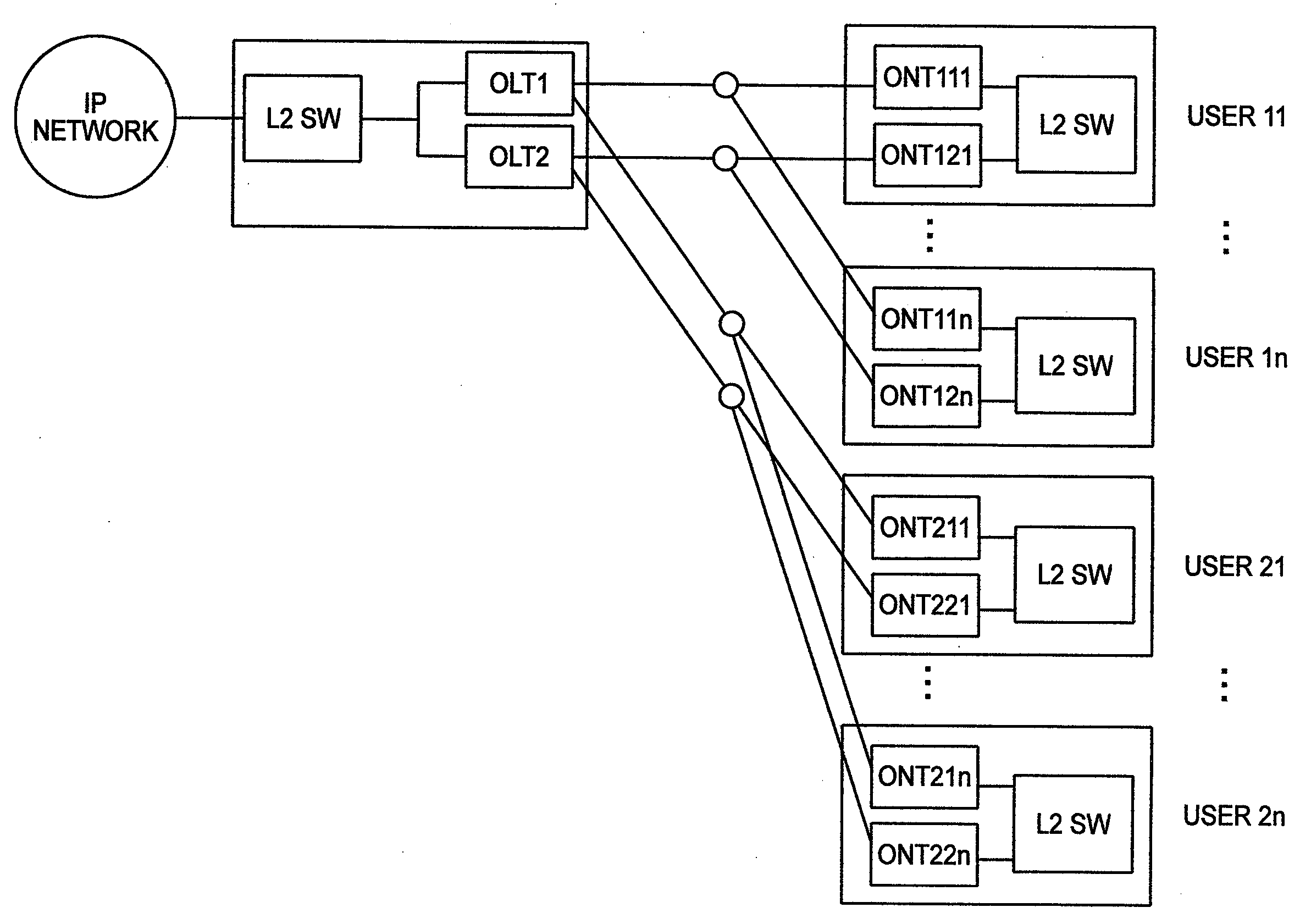
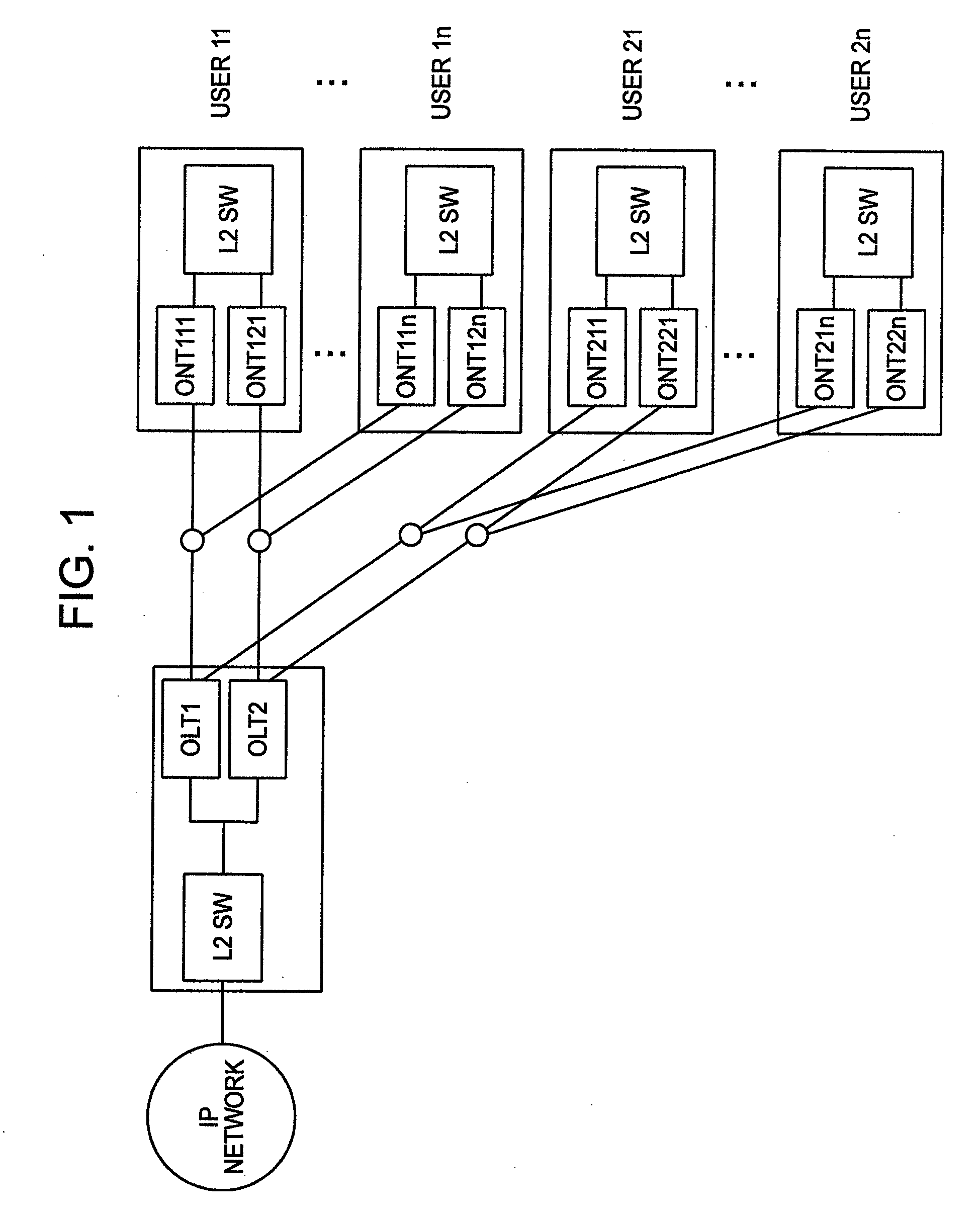
[0049]FIG. 1 is a figure of a network system that is a prerequisite of the present invention. Assume that all the users have implemented the 1+1 protection. A user 11 has implemented the 1+1 protection using a combination of OLT1 and ONT111 as well as OLT2 and ONT121. Likewise, a user in has implemented the 1+1 protection using a combination of OLT1 and ONT11n as well as OLT2 and ONT12n. Hereinafter, although the user 11 will be described, the same description is completely applied to other users, as well.

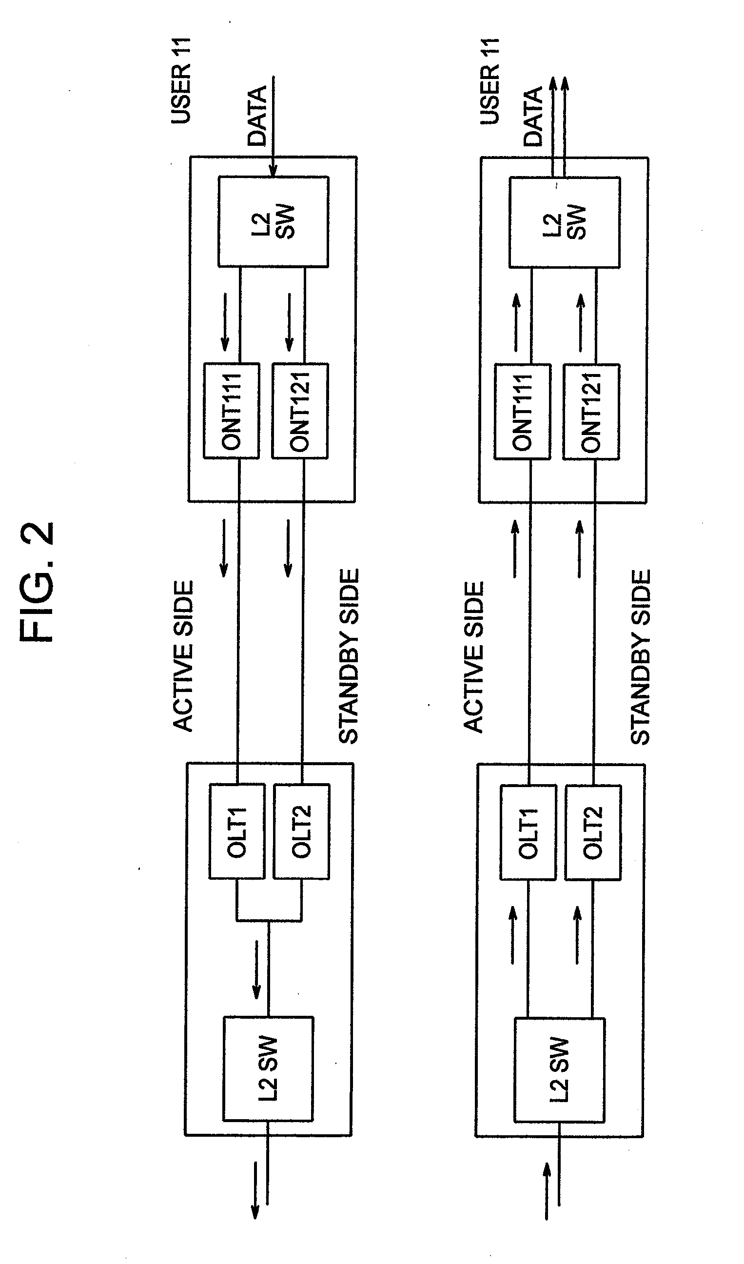
[0050]FIG. 2 shows an actual communication data flow in the redundant system of FIG. 1. Here, assume that OLT1 and ONT111 are on the actual side and OLT2 and ONT121 are on the standby side. In the direction from ONT to OLT, first, data is copied by L2SW and input to ONT111 and ONT121, respectively. These data pass through optical fibers and reach OLT1 and OLT2, respectively. The active OLT1 sends the received data as it is, while the standby OLT2 discards the data. This can prevent...

embodiment 2

[0076]Moreover, as a second embodiment, a case of using WDM (Wavelength Division Multiplexing) using a plurality of wavelengths of light is shown in FIG. 26. OLT1 and OLT2 communicate with ONT by using different wavelengths, respectively. Both OLT1 and OLT2 use two wavelengths, respectively, i.e., a total of four wavelengths are used here. The lines forming the redundant system by OLT1 and OLT2 are combined by MuxDemux 2601 and connected to one optical fiber. With lights of different wavelengths over this one optical fiber, two kinds of communications of OLT1 and ONT111 as well as OLT2 and ONT121 are multiplexed, for example. This embodiment corresponds to a case where the 1+1 protection system is implemented with one optical fiber by using WDM. Also here, completely the same as the foregoing description is applied. FIG. 27 shows an example of the table of management information 1005 in this embodiment. This table is the same as that of Embodiment 1 except that the currently-used wa...

embodiment 3

[0077]As a third embodiment, a case where a certain failure occurs in OLT and the switching active side is performed is shown in FIG. 28, FIG. 29, and FIG. 30. FIG. 28 shows the timing of switching active side, FIG. 29 shows the PON receiving function of OLT, and the others are all the same as those of Embodiment 1. A difference between FIG. 28 and FIG. 7 lies in that a notification of a time of failure occurrence is received in stead of reading the next starting time of autodiscovery procedure from the table of management information. Accordingly, the function of switching active side 1002 in OLT notifies the PON receiving function of OLT 1004 of the last time of grant before the failure occurrence. Moreover, when detecting the sequence of the last data in the receiving queue 1103 in the PON receiving function of OLT 1004 of FIG. 29, the queue may be empty depending on the timing. For this reason, a memory function of sequence number 2901 for storing the sequence number of the last...


PUM


Abstract

A duplicate system includes an active side (0 side) and a standby side (1 side). An OLT includes an autodiscovery function which, when the OLT is active, determines the next starting time of autodiscovery procedure of the standby side and notifies the standby side of the above starting time, a table of management information that holds the line information of a partner with which the OLT forms the duplicate system and the next starting time of autodiscovery procedure of the OLT, and a function of switching active side that calculates a timing of switching active side. A function of receiving data from ONT in the OLT includes a function of detecting data sequence number and a function of detecting queue length. Moreover, a function of sending data of ONT includes a function of assigning sequence number and a function of discarding data.

Description

INCORPORATION BY REFERENCE[0001]The present application claims priority from Japanese applications JP2008-089132 filed on Mar. 31, 2008 and the content of which is hereby incorporated by reference into this application.BACKGROUND OF THE INVENTION[0002]The present invention relates to data transmission equipment that shares one optical fiber with a plurality of users, and more specifically, relates to the data transmission equipment of a passive optical network (PON).[0003]Today, as the communication method used for Internet access, FTTH (Fiber To The Home) using optical fibers is becoming popular in place of ADSL (Asynchronous Digital Subscriber Line) that uses telephone lines. One of the methods of realizing this FTTH is EPON (Ethernet Passive Optical Network) formulated by Institute of Electrical and Electronics Engineers (IEEE). In EPON, one optical fiber from a central office of a common carrier is shared with a plurality of (as many as 32) users, and the optical fiber is branch...

Claims


Application Information

Patent Timeline
IPC IPC(8): H04J14/00H04B10/03H04B10/032H04B10/27H04B10/272H04B10/524H04B10/54H04J14/08H04L12/44
CPCH04Q11/0067H04Q2011/0081H04Q2011/0073
Inventor OISHI, TAKUMITAKASE, MASAYUKI
Owner HITACHI LTD
Why Eureka
Try Eureka