Chambered airfoil cooling

Active Publication Date: 2009-10-01
RAYTHEON TECH CORP
View PDF20 Cites 16 Cited by
  • Summary
  • Abstract
  • Description
  • Claims
  • Application Information

AI Technical Summary

Benefits of technology

[0006]The exemplarily cavity includes dividers disposed between the baffle and the internal walls of the cavity that direct air to leading and trailing edge chambers to prevent uneven distribut

Problems solved by technology

The warmer air mixes with the cooler air causing a non-uniform temperature of the cooling air that results in non-uniform cooling along the airfoil.
This can resul

Method used


Image

  • Chambered airfoil cooling
  • Chambered airfoil cooling
  • Chambered airfoil cooling

Examples


Example

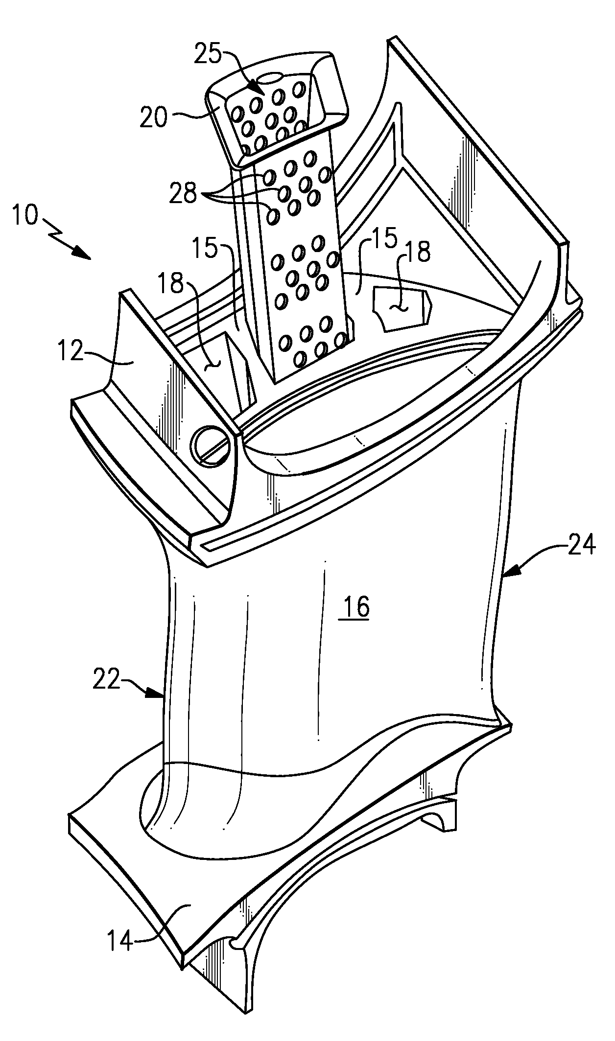
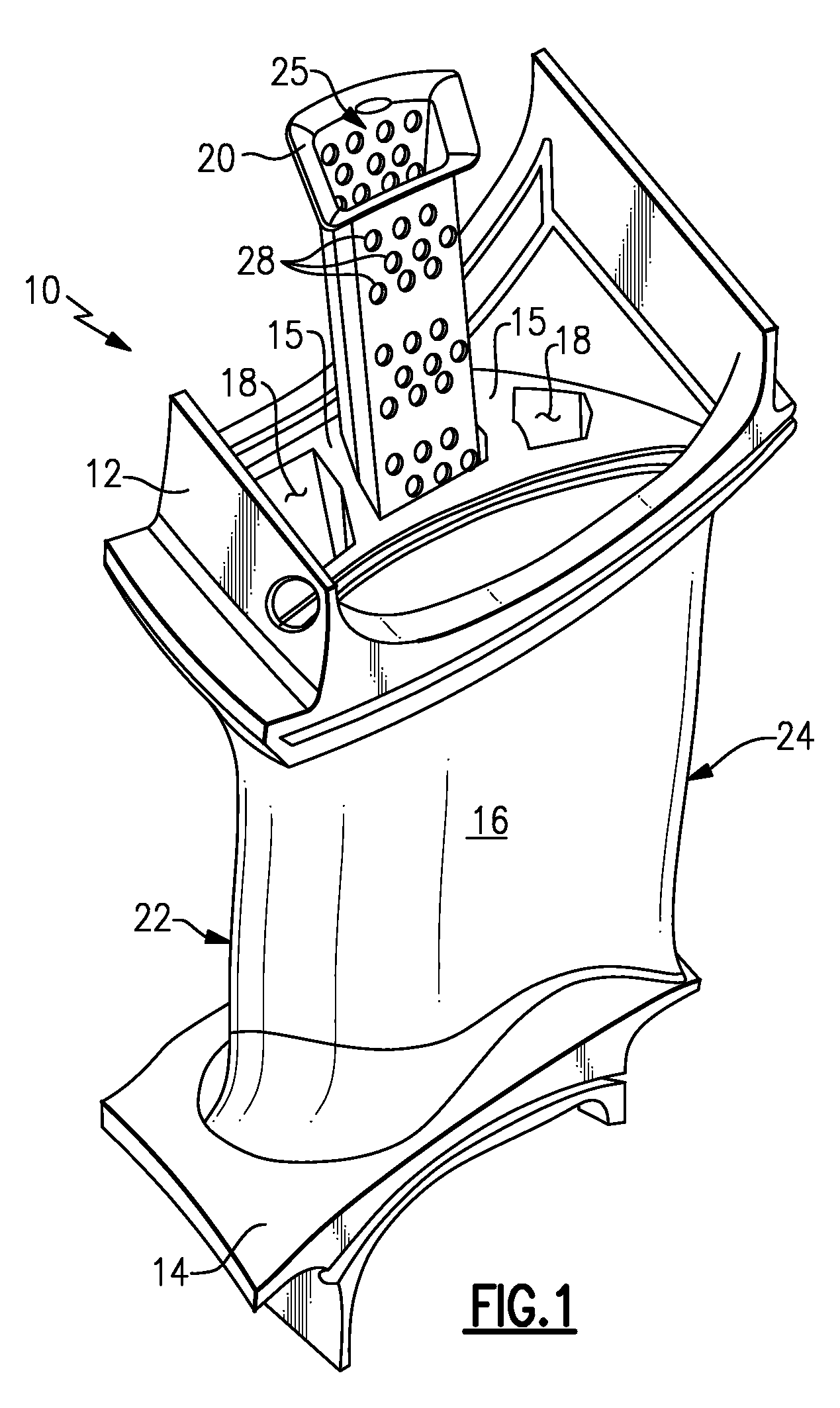
[0018]Referring to FIG. 1, a turbine vane 10 includes an outer flange 12 and an inner flange 14. Extending between the outer flange 12 and the inner flange 14 is an airfoil 16. The airfoil 16 includes a plurality of cavities 18 separated by ribs 15 through which cooling air is flown. A baffle 20 is inserted into at least one of the cavities 18. The baffle 20 includes a plurality of openings 28 that direct cooling air outwardly against an interior surface, or hot wall of the cavities 18. The airfoil 16 includes a leading edge 22 and a trailing edge 24. The airfoil assembly 16 is exposed to the extreme temperature conditions of hot gas flow emanating from the combustion chamber of the gas turbine engine. Accordingly, the cooling airflow through the cavities 18 provide a cooling function to remove at least some of the heat that is encountered by the airfoil 16.

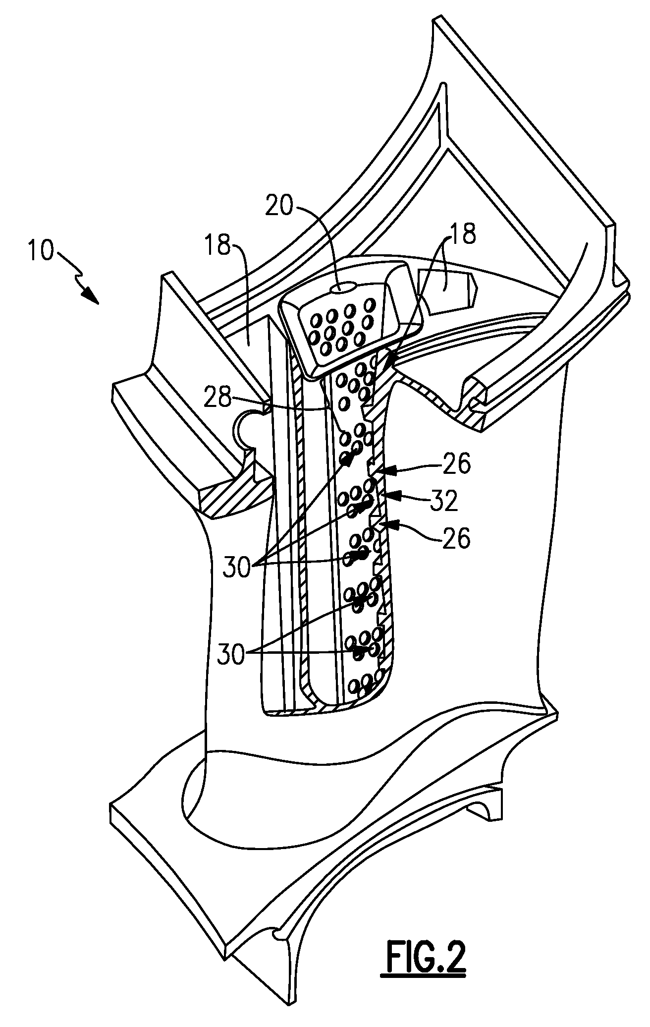
[0019]Referring to FIG. 2, the turbine vane assembly 10 is shown with one of the cavities 18 cutaway to expose the plurality of...


PUM


Abstract

An airfoil assembly includes an airfoil with at least one cavity that is in communication with a source of cooling air. A baffle is disposed within that cavity and includes a plurality of openings for directing cooling air against the hot wall. A plurality of dividers extends between the baffle walls and the internal cavity to direct cooling air toward one of a leading edge chamber and a trailing edge chamber.

Description

BACKGROUND OF THE INVENTION[0001]This disclosure generally relates to an airfoil including an internal cooling chamber and baffle. More particularly, this disclosure relates to an airfoil including chambers for preferentially directing cooling air within the cooling chamber.[0002]An airfoil utilized within a gas turbine engine includes a cooling chamber within which cooling air flows to remove heat from an inner surface of a wall exposed to extreme temperatures. A baffle within the cooling chamber includes a plurality of openings for directing air to impinge directly against the inner surface of the hot wall. The impingement of the cooling air against the hot wall improves cooling efficiencies.[0003]Disadvantageously, cooling air that has impinged against the hot wall is warmed and flows toward an exhaust opening opposite from the inlet. The warmer air mixes with the cooler air causing a non-uniform temperature of the cooling air that results in non-uniform cooling along the airfoil...

Claims


Application Information

Patent Timeline
IPC IPC(8): F01D5/18
CPCF05D2260/201F01D5/188
Inventor CHON, YOUNG H.PROPHETER-HINCKLEY, TRACY A.COUCH, ERIC L.
Owner RAYTHEON TECH CORP
Why Eureka
Try Eureka