Clutch control device

a control device and lockup technology, applied in the direction of gearing control, gearing elements, clutches, etc., can solve the problems of power transmission necessarily producing a rotation transmission loss, driver is not necessarily always constant, and it is difficult to control the amount of slip at a target value simply by feedback control, so as to improve the responsiveness of slip control

Inactive Publication Date: 2009-10-01
AISIN AW CO LTD
View PDF6 Cites 16 Cited by
  • Summary
  • Abstract
  • Description
  • Claims
  • Application Information

AI Technical Summary

Benefits of technology

[0010]Accordingly, it is an object of the present invention to provide a clutch control system that enables slip control that is both highly responsive and stable, even in a high engine speed, high engine torque state.
[0012]In the above system, when it is determined that the deviation between the target rotational speed difference and the actual rotational speed difference is outside of the predetermined range, the feedback value correcting unit sets a correction value and corrects the feedback oil pressure value by the correction value. Therefore, when the actual rotational speed difference is outside of the predetermined range of the target rotational speed difference, the feedback oil pressure value is corrected until the actual rotational speed difference falls within the predetermined range. The actual rotational speed difference can therefore be rapidly brought closer to the target rotational speed difference. When the actual rotational speed difference falls within the predetermined range for the target rotational speed difference, control is switched to normal feedback control by the feedback value calculating unit in order to assure stability, i.e. to avoid overshooting. As a result, both fast responsiveness and stability can be achieved even at, for example, a high engine speed, high engine torque region, enabling slip control that can be used in practical applications.
[0015]Thus, in the clutch control system of the present invention, the feedback value correcting unit raises the present (set) correction value as the rotational speed of the input shaft of the automatic speed change mechanism becomes higher and, therefore, rapidity of responsiveness in slip control is improved.
[0017]In one preferred embodiment, the clutch control system (for example, see FIGS. 1, 2, 3, and 8) further includes a feed-forward value learning unit that converts the correction value, that has been set responsive to a determination by the deviation out-of-range determining unit that a deviation which was outside of the predetermined range has moved to within the predetermined range, to a next feed-forward oil pressure value calculated by the feed-forward value calculating unit. Therefore, the actual deviation will fall within the predetermined value from the beginning of slip control, according to the feed-forward oil pressure value obtained by learning of the oil pressure command value and conformance of the actual rotational speed difference with the target rotational speed difference is significantly improved.

Problems solved by technology

Such a hydraulic power transmission necessarily produces a rotation transmission loss after starting of the vehicle in motion.
However, accelerator operation by a driver is not necessarily always constant and, when the engine torque varies, it is difficult to control the amount of slip at a target value simply by feedback control only.
However, at such a higher engine speed, in a higher engine torque region, sensitivity of actual rotational speed difference to an oil pressure value based on variation in engine speed and variation in torque, is relatively small as compared to that at a low engine speed, low engine torque region.
Therefore, even if slip control is conducted as taught in Japanese Patent No. 2985102 or Japanese Patent No. 3098667, a delay (lag time) of about several seconds will occur before the amount of slip converges with a target value dependent on variation in engine output, making such control impractical.

Method used


Image

  • Clutch control device
  • Clutch control device
  • Clutch control device

Examples


Embodiment Construction

[0028]A preferred embodiment of the present invention will now be described with reference to FIGS. 1 through 10.

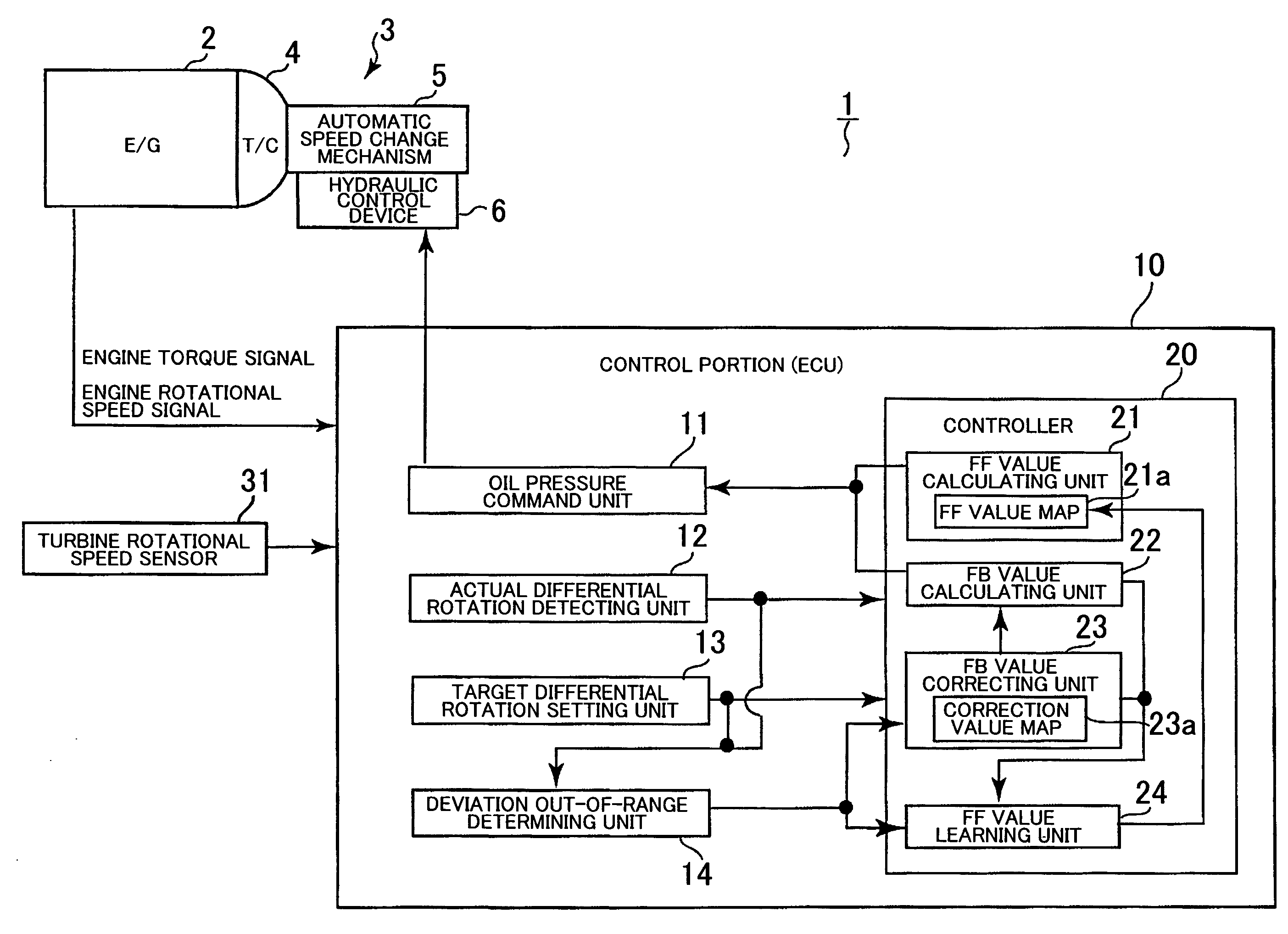
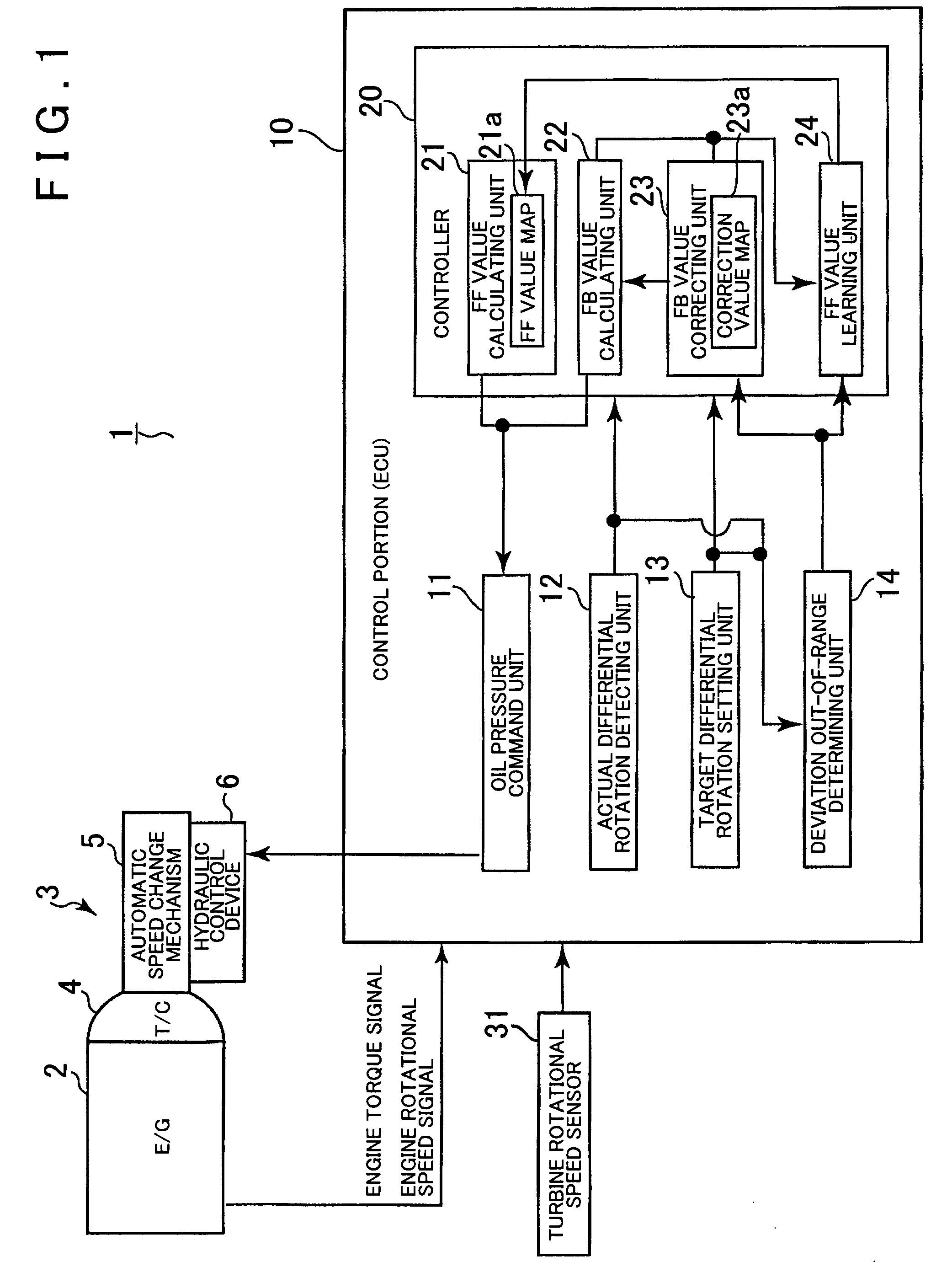
[0029]First, a hydraulic control circuit of the present invention will be described with reference to FIG. 1 and FIG. 10. As shown in FIG. 1, an automatic transmission 3, connected to an engine 2, generally includes a torque converter 4, an automatic speed change mechanism 5, and a hydraulic control device 6. The torque converter 4 is provided between the output shaft of the engine 2 and the input shaft of the automatic speed change mechanism 5.

[0030]As shown in FIG. 10, the torque converter 4 has a pump impeller 4a connected to an input shaft 3a (i.e., the output shaft of the engine 2) of the automatic transmission 3, a turbine runner 4b to which rotation of the pump impeller 4a is transmitted through a working fluid, and a stator 4c which is provided between the pump impeller 4a and the turbine runner 4b which is restricted to rotation in one direction by a one-way clut...


PUM


Abstract

An oil pressure command value for slip-control of a lock-up clutch of a torque converter is calculated based on a feed-forward oil pressure value calculated by an FF value calculating unit and a feed-back oil pressure value calculated by a feedback value calculating unit. When the feedback oil pressure value is calculated, a deviation out-of-range determining unit determines whether a deviation between actual rotational speed difference and target rotational speed difference is outside of a predetermined range. If the deviation is outside of the predetermined range, a feedback value correcting unit calculates a correction value and corrects the feedback oil pressure value. Therefore, when the deviation is outside of the predetermined range, the actual rotational speed difference is brought into convergence with the target rotational speed difference with rapid response. When the deviation falls within the predetermined range, normal feedback control is adopted to assure stability without overshooting, even in a high engine speed, high engine torque state.

Description

INCORPORATION BY REFERENCE[0001]The disclosure of Japanese Patent Application No. 2008-093355 filed on Mar. 31, 2008 including the specification, drawings and abstract is incorporated herein by reference in its entirety.BACKGROUND OF THE INVENTION[0002]1. Field of the Invention[0003]The present invention relates to a control device for a lock-up clutch of a vehicle torque converter and for a clutch in a starting device or the like that does not use a hydraulic power transmission such as a torque converter. More particularly, the present invention relates to a control device for controlling clutch slip, i.e. controlling a clutch in a state of slipping or “slip state.”[0004]2. Description of the Related Art[0005]In general, an automatic transmission mounted in a vehicle or the like includes a hydraulic power transmission such as a torque converter for providing power transmission while absorbing a rotational speed difference between output rotation of an engine and input rotation of a...

Claims


Application Information

Patent Timeline
Patent Type & Authority Applications(United States)
IPC IPC(8): B60W10/04
CPCF16D48/066F16D2500/3024F16D2500/70406F16D2500/70426Y10T477/79F16D2500/70631F16H61/143F16H2061/145Y10T477/78F16D2500/7061
Inventor NAGAMI, KIYOSHIUMEMURA, YOSHIOHASHIZUME, MAKOTOKATO, TAKASHI
Owner AISIN AW CO LTD
Why Eureka
Try Eureka