Electric cable drive device and electric brake device

a technology of electric brake and drive device, which is applied in the direction of brake system, machine/engine, braking, etc., can solve the problems of large housing, difficult to equalize the right and left braking forces, and troublesome assembly work, etc., to achieve high brake force control precision, simple structure, and enhanced safety

Active Publication Date: 2009-10-01
HI-LEX CORPORATION
View PDF11 Cites 43 Cited by
  • Summary
  • Abstract
  • Description
  • Claims
  • Application Information

AI Technical Summary

Benefits of technology

[0018]In the electrically driven parking brake assembly of the Patent Publication 4, it is not apparent how the Hall effect sensor is provided, but in the case that a purchased DC motor is employed, a rotary encoder is composed in the speed reducer by mounting a magnet on a rotating member such as an intermediate gear (or final gear connected to the lead screw) for two stage speed reduction in the transmission, and by providing a Hall effect sensor on the gear housing. In this case, high precision detection of the quantity of the movement of the cable can not be achieved without providing many Hall effect elements and magnets for detection, thereby the composition of the rotary encoder and the speed reducer becomes complicated increasing the number of parts and man-hour of the manufacturing work.
[0071]Since the electrically driven brake device of this invention uses the above described cable drive device, the structure is simple and further the precision of the brake force control is high. And in the case that the load sensor is used, the safety can be enhanced. Further, in the case that the equalizer is used, the right and left brake force can be equalized. In the case that emergency release mechanism is provided, in case of the electric system failure, the brake can be released manually. In the case that the wrapping connector drive type speed reducer is used, noises can be reduced.

Problems solved by technology

However, it needs the spline hubs and the splines complicating the structure and makes the assembling work be troublesome.
On the other hand, the brake control device of the Patent Publication 2 has relatively simple structure and can equalize the quantity of the right and left operation, but it is difficult to equalize the right and left braking forces.
Therefore, the housing becomes large requiring the wide mounting space.
In this case, high precision detection of the quantity of the movement of the cable can not be achieved without providing many Hall effect elements and magnets for detection, thereby the composition of the rotary encoder and the speed reducer becomes complicated increasing the number of parts and man-hour of the manufacturing work.
In the electrically driven parking brake assembly 219 of the Patent Publication 4, since no more operation than to rotate the override gear 242 in the speed reducer by rotating the override cable 243 is necessary, the operating physical force is needed not to be strong, but many rotations are needed making it troublesome in the case of manual release of the brake.

Method used


Image

  • Electric cable drive device and electric brake device
  • Electric cable drive device and electric brake device
  • Electric cable drive device and electric brake device

Examples


Embodiment Construction

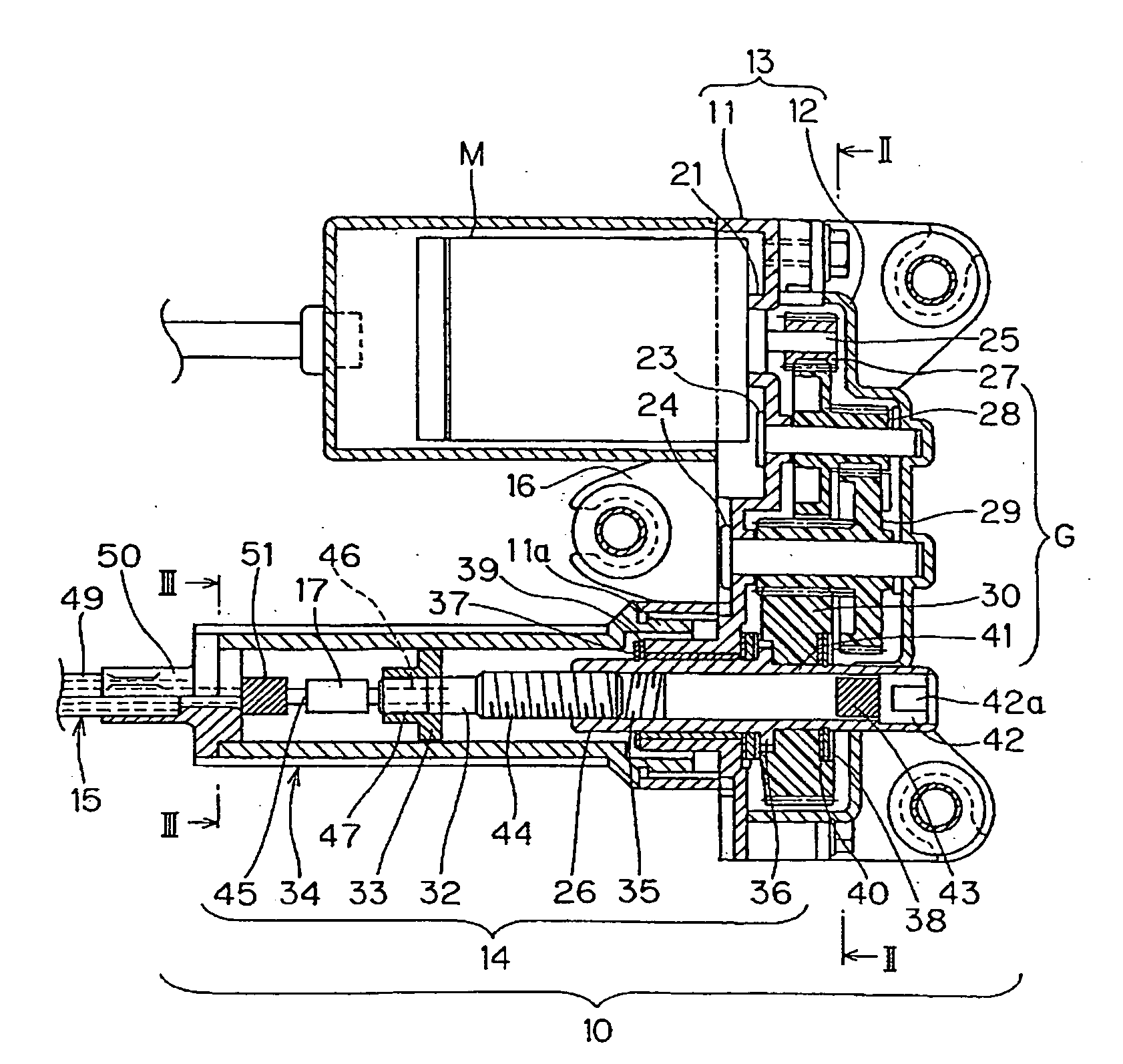
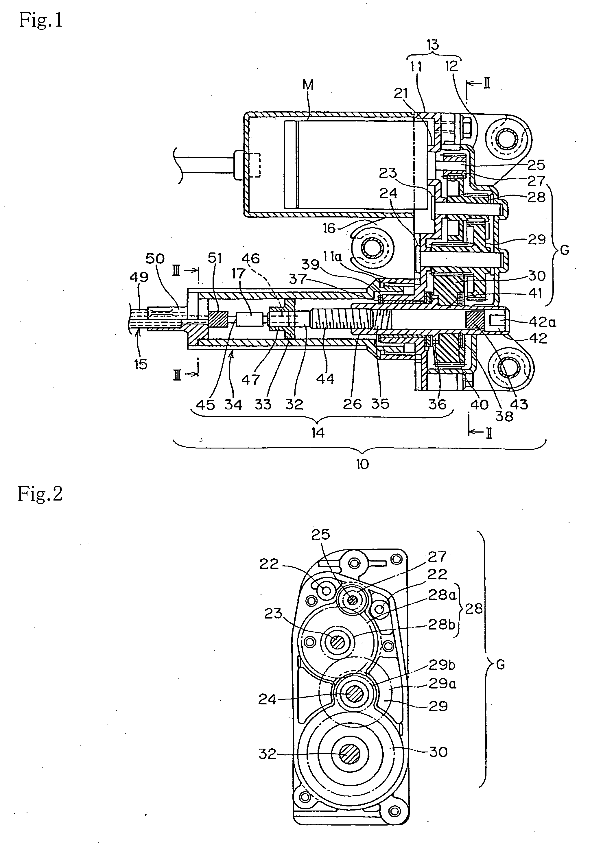
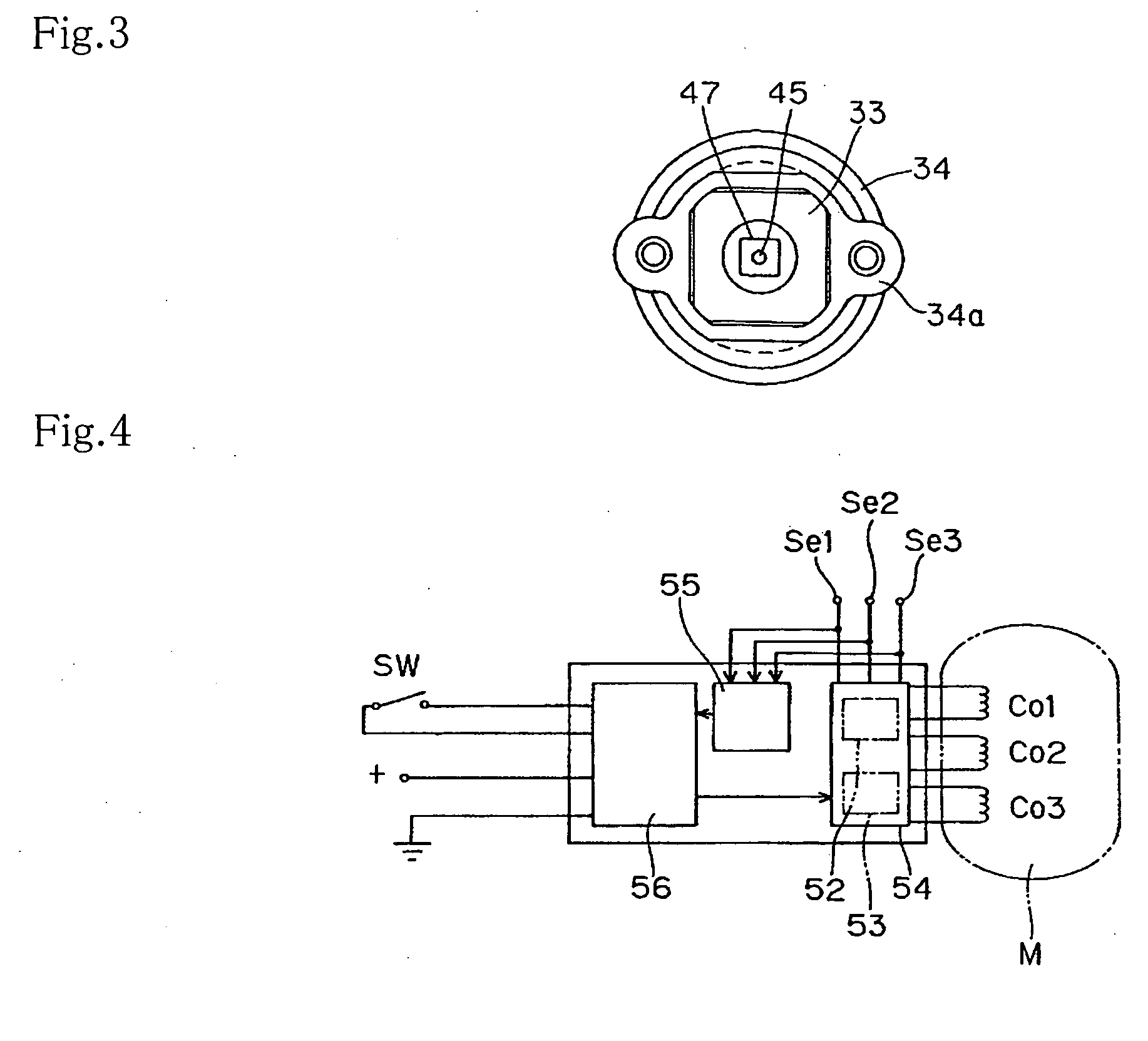
[0101]The cable drive device 10 in FIG. 1 is provided with a housing 13 composed of a body 11 and a cover 12, a motor M mounted on the housing, a speed reducer G which reduces the speed of the motor rotation being accommodated in the housing 13, a screw-nut mechanism (rotation / linear motion transducer(or converter)) 14 connected to the output of the speed reducer, and a control cable 15 reciprocatingly driven by the screw-nut mechanism. The reference numeral 16 is a base bracket holding the housing 13, and the reference numeral 17 is a load sensor for detecting the load of an inner cable 45 of the control cable 15 by being intervened in the midway of the control cable 15. The load sensor can be omitted. However, as described later, its output is preferable to be used for the safety of the cable drive devices and various devices in which it is used, particularly for the safety of parking brake devices.

[0102]In the body 11 of the housing 13, a mounting pedestal 21 for mounting the mot...


PUM


Abstract

An cable drive device (10) having a motor (M), a speed reducer (G), a nut member (26) connected to the speed reducer, a rod (32) screwed to the nut member (26) and guided by a guide member (34) so as not to rotate, a control cable (15) composed of an inner cable (45) connected to the rod and a guide tube (49) for guiding the inner cable, a sensor for detecting the amount of operation of the cable based on the amount of rotation of the speed reducer (G), and a load sensor (17) for detecting a load applied to the cable. An electric brake device can be obtained by connecting the control cable and a brake mechanism of the cable drive device (10).

Description

FIELD OF THE INVENTION [0001]This invention relates to an electric cable drive device and electrical brake device for automobiles using the said cable drive device. The automobiles include motorbikes, autocycles, power-assisted bicycles, golf carts, and forklifts.BACKGROUND ARTS[0002]Patent Document 1) Japanese Translation of PCT International Application No. 2001-513179[Patent Document 2] Japanese Published Patent Application No. H8-295210[Patent Document 3] Japanese Published Patent Application No. 2004-161063[Patent Document 4] Japanese Published Patent Application No. 2602-205627[0003][Patent Document 5] U.S. Pat. No. 6,386,338[Patent Document 6] Japanese Published Patent Application No. 2002-272076[0004]In the Patent Document 1, a parking brake 200 for vehicles, as shown in FIG. 25, is disclosed. In this parking brake 200, a gear 201 is formed on the periphery and a spline hub is formed in its inner periphery, and therewith, it is provided with a component member 202 being supp...

Claims


Application Information

Patent Timeline
Patent Type & Authority Applications(United States)
IPC IPC(8): B60T13/74F16H35/02F16D65/28
CPCB60T13/746F16H25/2021Y10T74/18528Y10T74/18576Y10T477/853B60T13/74B60T7/02F16D65/14F16D65/28
Inventor SANO, RITSUIMAKURA, TATSUYAOKAMOTO, CHIKASHI
Owner HI-LEX CORPORATION
Why Eureka
Try Eureka