Electronic Controller for Power Converter and Motor Drive Circuit

a technology of motor drive circuit and electronic controller, which is applied in the direction of electric controller, program control, instruments, etc., can solve the problems that cannot be expected shortening the response time from a-d conversion (input process) to outputting (output process) of a command value free of variations, so as to shorten the control cycle and shorten the response time from input process to output process, the effect of shortening the control cycl

Inactive Publication Date: 2009-10-01
HITACHI LTD
View PDF5 Cites 5 Cited by
  • Summary
  • Abstract
  • Description
  • Claims
  • Application Information

AI Technical Summary

Benefits of technology

[0013]The present invention was developed to solve the aforementioned problems and is intended to provide an electronic controller capable of surely performing an input process and an output process at appropriate timing by use of a simple circuit constitution and effectively realizing shortening of the control cycle, shortening of the response time from the input process to the output process, lightening of the processing load of an operation means, and improvement of the control accuracy.
[0024]Additionally, the input process, operation, and output process are executed in parallel (the processing periods are overlaid partially), so that the control cycle can be shortened, and the response time from the input process to the output process can be shortened, thus the response and control accuracy can be effectively improved.
[0025]Further, the operation means does not need to execute a start process of the input means and / or a start process of the output means, so that the load on the operation means can be lightened and the lightened load can be allocated to other processes.
[0026]Furthermore, the input processing means outputs an input process completion signal, and the operation means, on the basis of a signal inputted to it and the operation results, changes the timing for outputting at least one of the input process start signal, output process start signal, and operation start signal by the timer means, thereby can switch the control mode.
[0031]Additionally, the input process, operation, and output process can be executed in parallel, so that the control cycle can be shortened, and the response time from the input process to the output process can be shortened, thus the response and control accuracy can be effectively improved.
[0032]Further, the operation means does not need to execute a start process of the input means and / or a start process of the output means, so that the processing load on the operation means can be lightened and the lightened load can be allocated to other processes.

Problems solved by technology

However, effects of shortening the control cycle and shortening the response time from A-D conversion (input process) to outputting (output process) of a command value free of variations cannot be expected.

Method used


Image

  • Electronic Controller for Power Converter and Motor Drive Circuit
  • Electronic Controller for Power Converter and Motor Drive Circuit
  • Electronic Controller for Power Converter and Motor Drive Circuit

Examples


first embodiment

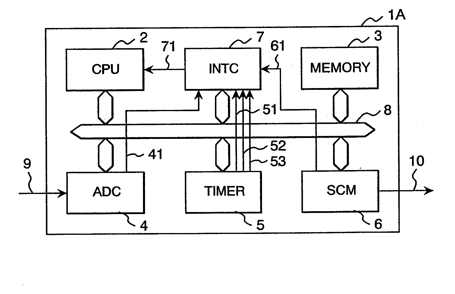
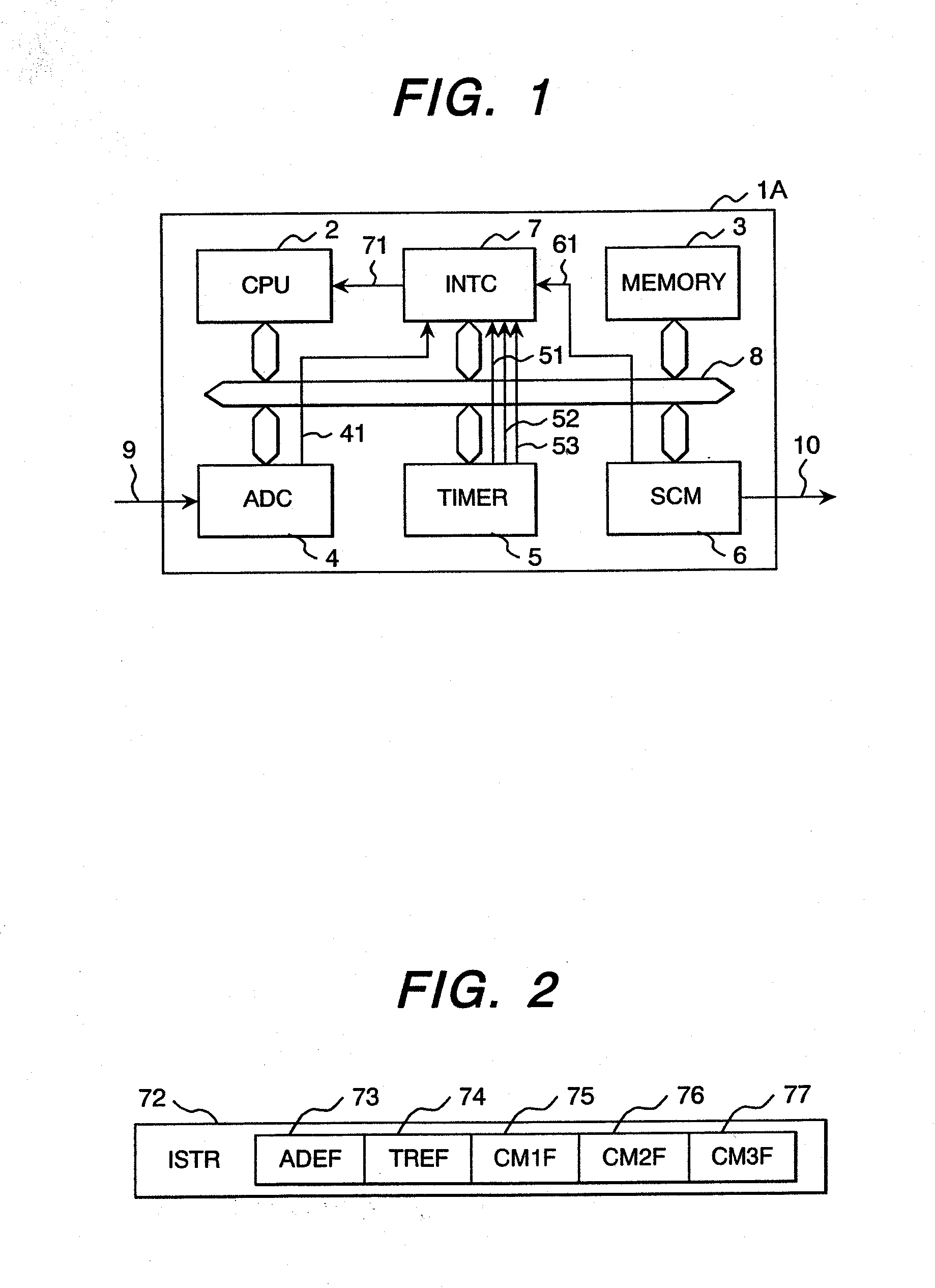
[0071]FIG. 1 is a schematic block diagram showing the first embodiment of the electronic controller relating to the present invention.

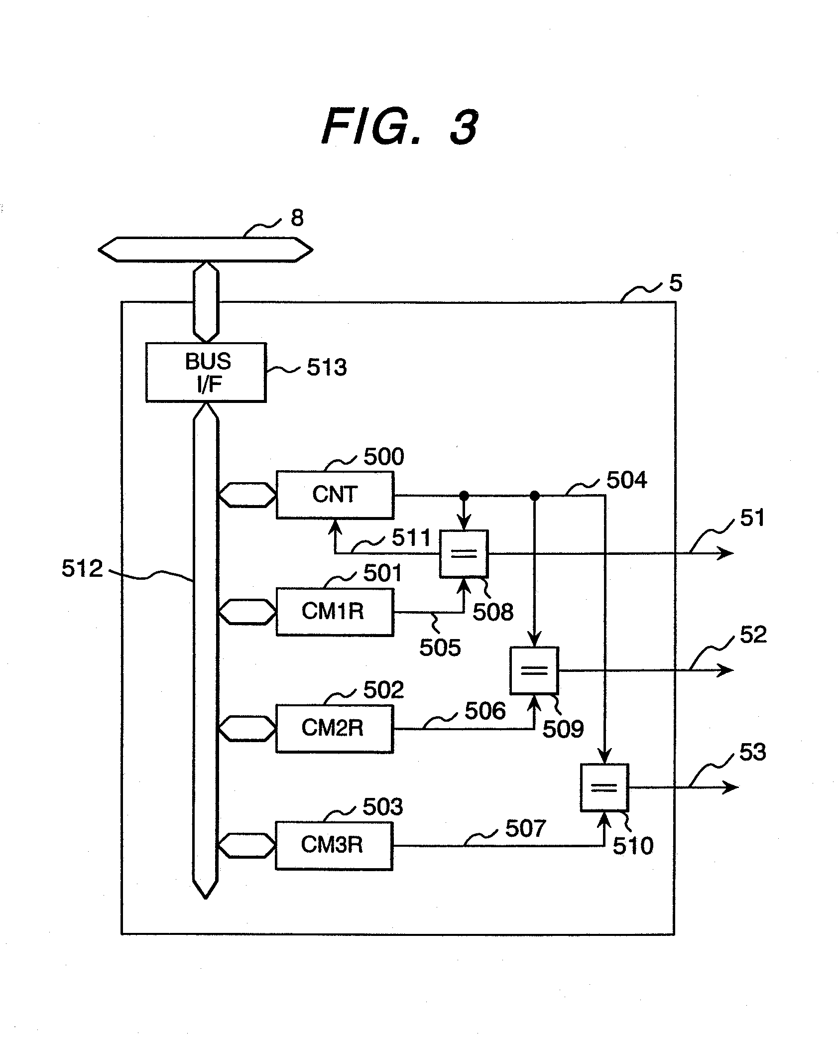
[0072]An electronic controller 1A of the first embodiment shown in the drawing has a central processing unit (CPU) 2, a memory 3, an A-D converter (ADC) 4 as an input means for fetching an analog signal (detection signal) 9 from one or a plurality of sensors externally arranged and converting it to a digital value, a timer 5 for outputting first, second, and third compare match signals 51, 52, and 53 at predetermined timing (will be described later), a serial communication module (SCM) 6 as an output means for transferring data to another device (to be controlled) via a serial transmission path 10, and an interruption controller (INTC) 7 for receiving the compare match signals 51, 52, and 53 outputted by the timer 5, an A-D conversion completion signal 41 outputted by the A-D converter (ADC) 4, and a transmission completion signal 61 outputted by the ...

second embodiment

[0141]FIG. 14 is a schematic block diagram of the second embodiment of the electronic controller relating to the present invention.

[0142]An electronic controller 1B of the second embodiment shown in the drawing is basically the same as the electronic controller 1A of the first embodiment shown in FIG. 1, though the respect that the A-D converter (ADC) 4 and the serial communication module (SCM) 6 respectively have dynamic memory access controllers (DMAC) 410 and 610 is different. The DMAC 410 has a function for transferring data converted by the A-D converter (ADC) 4 to the memory 3. Further, the DMAC 610 has a function for transferring data of the memory 3 to the serial communication module (SCM) 6 and starting the data transmission of the SCM. Here, the data transfer by the DMACs 410 and 610 is called DMA transfer.

[0143]FIG. 15 shows a block diagram of an example of the A-D converter (ADC) 4 shown in FIG. 14. The ADC 4 in this example is basically the same as that shown in FIG. 5,...

third embodiment

[0190]FIG. 21 is a schematic block diagram of the third embodiment of the electronic controller relating to the present invention.

[0191]An electronic controller 1C of the third embodiment shown in the drawing is basically the same as the electronic controller 1A of the first embodiment shown in FIG. 1, though the respect that the compare match 2 signal (CM2S) 52 and the compare match 3 signal (CM3S) 53 of the timer 5 are respectively connected (outputted) to the A-D converter (ADC) 4 and the serial communication module (SCM) 6 is different.

[0192]The electronic controller 1C has the central processing unit (CPU) 2, the memory 3, the analog-digital converter (ADC) 4 for fetching the analog signal 9 inputted from one or a plurality of sensors and converting it to a digital value, the timer 5 for outputting the compare match signals 51, 52, and 53 at predetermined timing, the serial communication module (SCM) 6 for transferring data to another device via the serial transmission path 10,...


PUM


Abstract

The electronic controller fetches an external signal and performs an input process such as A-D conversion. Upon receipt of processing results for executing operations according to a predetermined program, an output process is performed for sending a signal to the outside board on operation results, a timer outputs at least two of an input process start signal for starting the input process, an output process start signal for starting the output process, and an operation start signal for starting the operation.

Description

[0001]This application is a continuation of pending U.S. patent application Ser. No. 10 / 980,772, filed Nov. 4, 2004, the disclosure of which is expressly incorporated by reference herein.CLAIM OF PRIORITY[0002]The present application claims priority from Japanese patent application serial no. 2003-374737, filed on Nov. 4, 2003, the content of which is hereby incorporated by reference into this application.BACKGROUND OF THE INVENTION[0003]The present invention relates to an electronic controller for repeatedly executing an input process (A-D conversion, etc.), operations (program execution), and an output process (output by a serial signal) in a predetermined cycle.[0004]In a power conversion system and a power supply system for controlling power and an industrial system and a traffic system for controlling a motor, a power converter and a motor drive circuit composed of many switching elements are controlled by an electronic controller, thus power conversion and motor driving are re...

Claims


Application Information

Patent Timeline
Patent Type & Authority Applications(United States)
IPC IPC(8): G06F1/26G06F3/05G05B19/042H02M7/48H03M1/12
CPCG05B19/0423
Inventor MORITA, YUICHIROSHIMAMURA, KOTAROTSUNEDOMI, KUNIHIKOIMURA, SHINYASASAKI, SHOJIYOKOYAMA, TAKANORI
Owner HITACHI LTD
Why Eureka
Try Eureka