Stop Position Control Apparatus for Internal Combustion Engine

a technology for controlling apparatus and internal combustion engine, which is applied in the direction of engine starters, electric control, instruments, etc., can solve the problems of low accuracy and convergence of the control of the crank stop position, and achieve the improvement of the accuracy of estimating the stop position of the crankshaft, high efficiency arithmetic operations, and controlled accurately

Inactive Publication Date: 2009-10-01
TOYOTA JIDOSHA KK
View PDF5 Cites 16 Cited by
  • Summary
  • Abstract
  • Description
  • Claims
  • Application Information

AI Technical Summary

Benefits of technology

[0007]The present invention was made to solve the abovementioned problems, and an object of the invention is to provide an apparatus which applies a control scheme adapted to stop and restart an internal-combustion engine automatically and which is capable of estimating a stop position of a crankshaft accurately in the internal-combustion engine.
[0019]According to a sixth aspect of the present invention, high controllability of a stop position of a crankshaft can be obtained since, if it is judged that friction is inaccurately estimated, control of the crank stop position is prohibited.

Problems solved by technology

In addition, according to Patent Document 2, although consideration is given to the causes of the deviation, since the desired stop position is adjusted considering various factors all together, control of the crank stop position is considered to be low in accuracy and in convergence.

Method used


Image

  • Stop Position Control Apparatus for Internal Combustion Engine
  • Stop Position Control Apparatus for Internal Combustion Engine
  • Stop Position Control Apparatus for Internal Combustion Engine

Examples


first embodiment

System Configuration According to First Embodiment

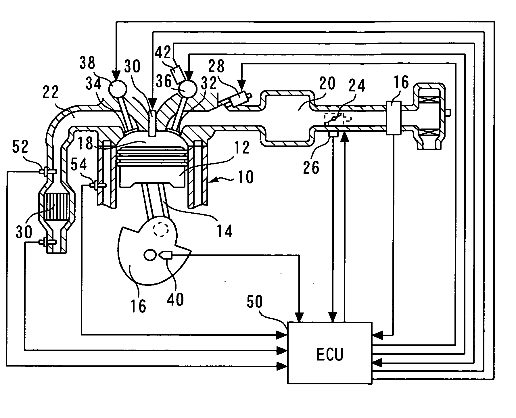
[0032]FIG. 1 is a diagram explaining a configuration of an internal-combustion engine 10 to which a stop position control apparatus for an internal-combustion engine is applied as a first embodiment of the present invention. The system of the present embodiment includes the internal-combustion engine 10. Also, the present embodiment assumes an inline four-cylinder engine as the internal-combustion engine 10. Each of cylinders of the internal-combustion engine 10 contains a piston 12. The piston 12 is coupled with a crankshaft 16 via a connecting rod 14. Each of the cylinders of the internal-combustion engine 10 also has a combustion chamber 18 formed atop the piston 12. An air intake passageway 20 and an exhaust passageway 22 are communicated with the combustion chamber 18.

[0033]The air intake passageway 20 includes a throttle valve 24. The throttle valve 24 is an electronically controlled throttle valve that can control an open posi...

second embodiment

[0138]A second embodiment of the present invention will now be described with reference to FIG. 11.

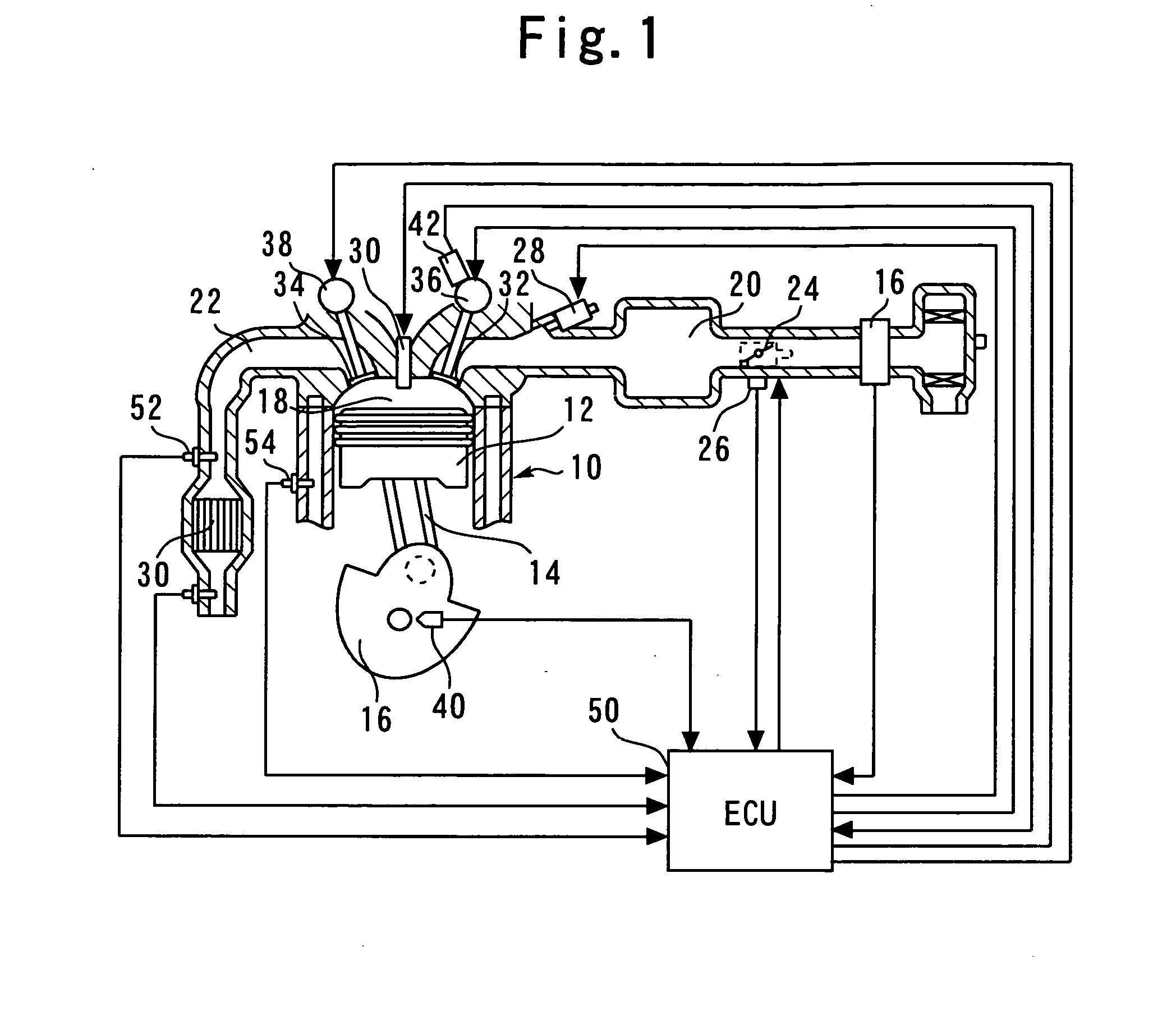
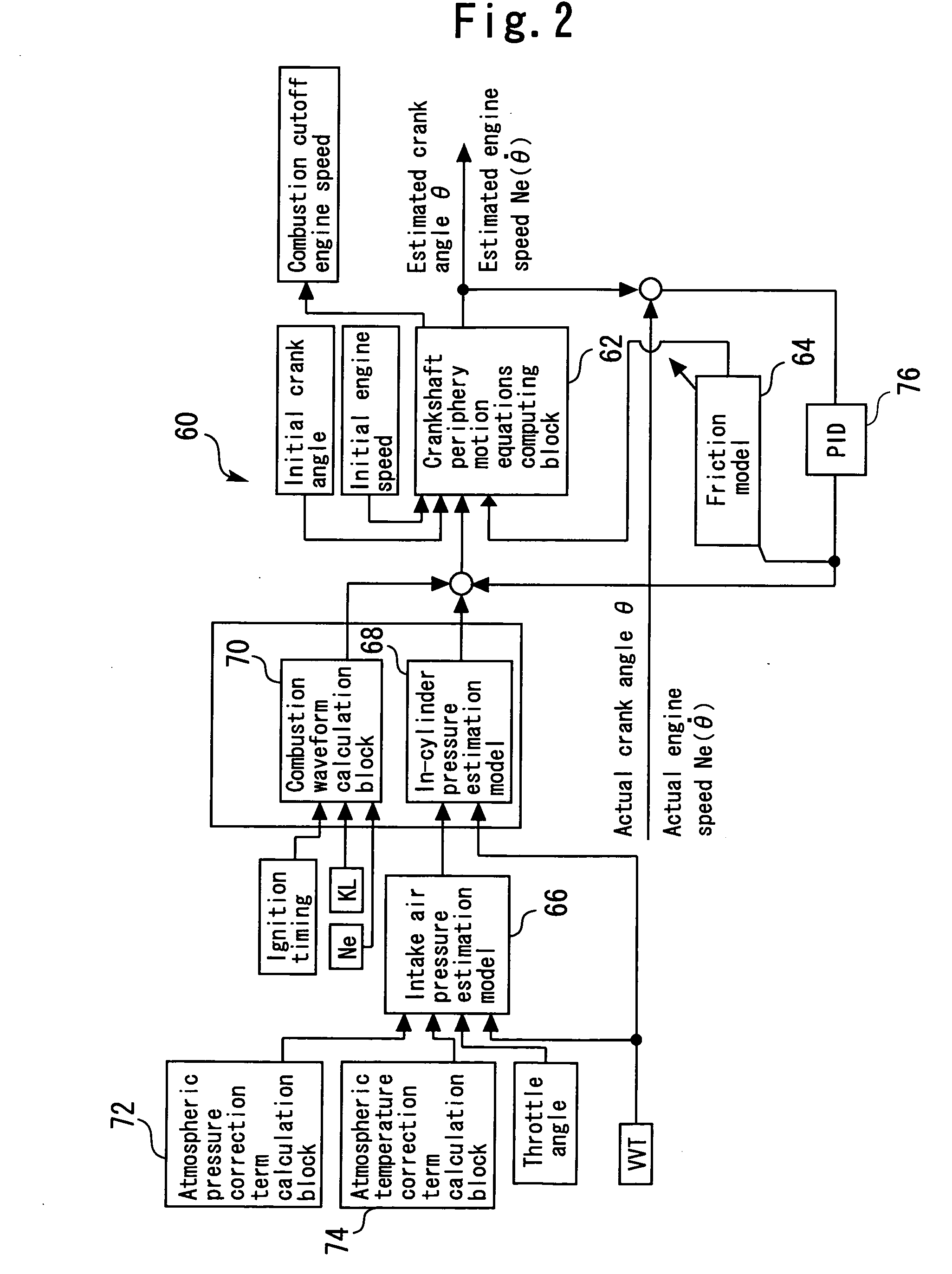
[0139]The system according to the second embodiment is implemented by adopting the hardware configuration shown in FIG. 1 and engine model 60 shown in FIG. 2 and by allowing the ECU 50 to execute a routine shown in FIG. 11 instead of the routine shown in FIG. 6.

[0140]The stop position of the crank in the internal-combustion engine 10 is appropriately controlled by using the above-described engine model 60 in order to improve the engine restartability during the execution of economical running control. To appropriately control the stop position of the crank, it is necessary to estimate the friction (friction torque TRQf) inside the internal-combustion engine 10 with high accuracy since the friction is a very influential factor. Magnitude of the friction usually depends on the lubricating oil temperature of the internal-combustion engine 10. The friction, however, is typically corrected ...

third embodiment

[0151]A third embodiment of the present invention will now be described with reference to FIG. 12.

[0152]The system according to the third embodiment is implemented by adopting the hardware configuration shown in FIG. 1 and engine model 60 shown in FIG. 2 and by allowing the ECU 50 to execute a routine shown in FIG. 12 instead of the routine shown in FIG. 11.

[0153]A system of the present embodiment differs from the system of the above-described second embodiment in terms only of a method of judging the difference between the cooling water temperature and the lubricating oil temperature. Hereunder, a description will be made mainly of the method in accordance with the routine shown in FIG. 12.

Detail Process in the Third Embodiment

[0154]FIG. 12 is a flowchart of the routine that the ECU 50 executes in the third embodiment of the present invention. In the routine of FIG. 12, if it is judged in step 300 that the internal-combustion engine 10 is currently in steady operation, an evaluatio...


PUM


Abstract

An engine model is configured so as to include a crankshaft periphery motion equations computing block, a friction model, an intake air pressure estimation model, an in-cylinder pressure estimation model, a combustion waveform calculation block, an atmospheric pressure correction term calculation block, and an atmospheric temperature correction term calculation block. While combustion is cut off, the friction model is learned and updated using estimated relating to the crank stop position calculated by the engine model and measured data relating to the crank stop position.

Description

TECHNICAL FIELD[0001]The present invention relates generally to apparatus for controlling a stop position of an internal-combustion engine. More particularly, the invention concerns a stop position control apparatus for an internal-combustion engine, the apparatus applying a control scheme adapted to stop and restart an internal-combustion engine automatically after a temporary stop of an associated motor vehicle.BACKGROUND ART[0002]Japanese Patent Application Laid-Open Publication No. 2004-293444 (Patent Document 1) discloses, as a conventional apparatus, an engine starter that executes control (economical running control) to stop and restart an internal-combustion engine automatically after an associated motor vehicle has come to a temporary stop. In order to smoothly restart the internal-combustion engine, this conventional apparatus is intended to optimize a stop position of a piston (a stop position of a crankshaft) during the automatic stop of the internal-combustion engine by...

Claims


Application Information

Patent Timeline
Patent Type & Authority Applications(United States)
IPC IPC(8): F02D45/00F02D17/00F02D29/02F02N11/08
CPCF02D41/009F02D41/042F02D41/123F02D41/2451F02D2041/0095Y02T10/48F02D2200/1006F02N11/0818F02N19/005F02N2019/008F02N2200/023F02D2200/023Y02T10/40F02D35/00F02D41/04F02D41/12F02D41/24
Inventor ADACHI, NORIYASU
Owner TOYOTA JIDOSHA KK
Why Eureka
Try Eureka