Internal pipe slot tool
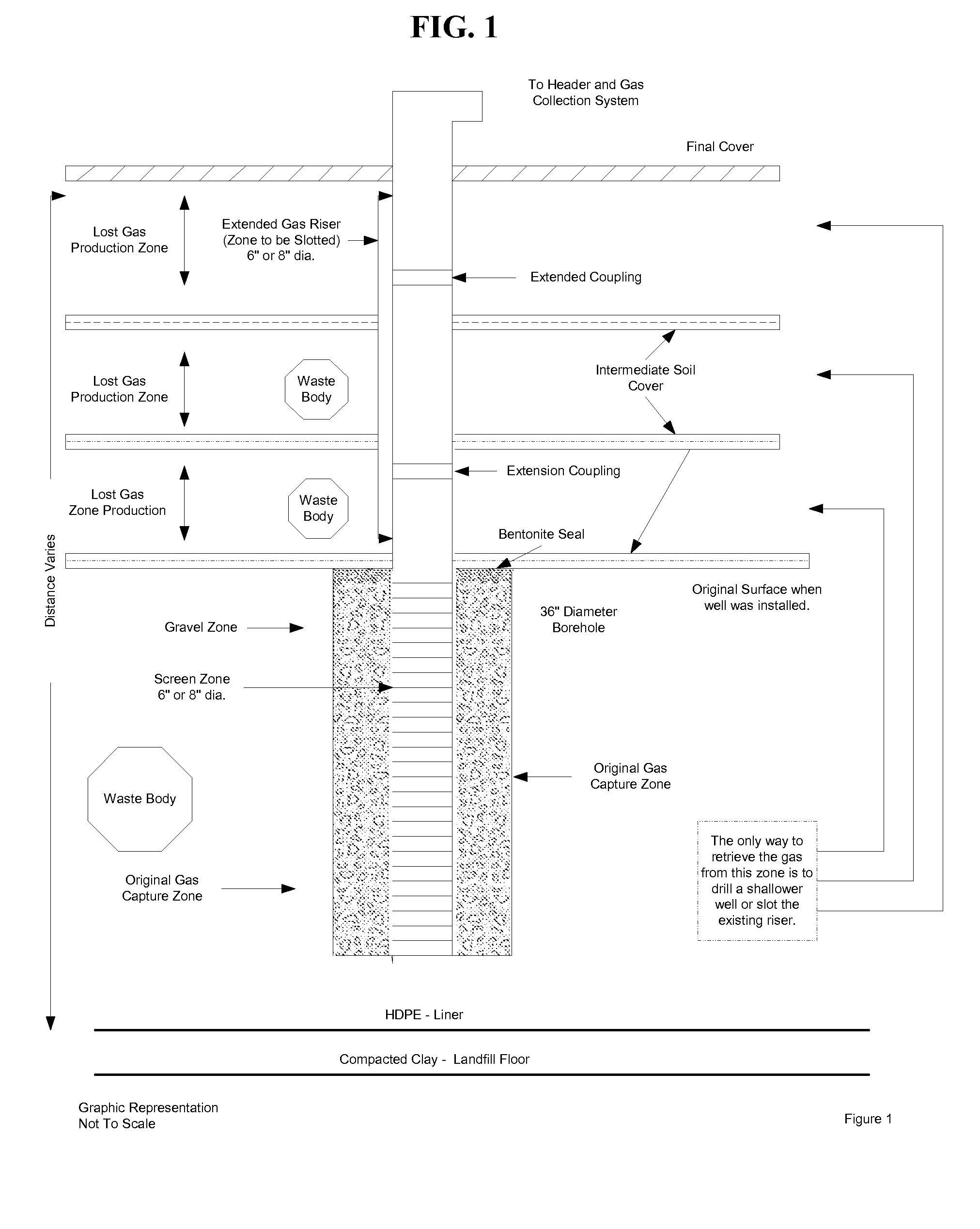
a technology of internal pipes and tools, applied in earth drilling, fluid removal, borehole/well accessories, etc., can solve the problems of escaping lfg emissions, a loss of the opportunity to capture and use a significant energy resource, and the extraction of lfg from upper elevations by shallower wells is a capital intensive process
- Summary
- Abstract
- Description
- Claims
- Application Information
AI Technical Summary
Benefits of technology
Problems solved by technology
Method used
Image
Examples
example i
Pneumatic Cutter Tool
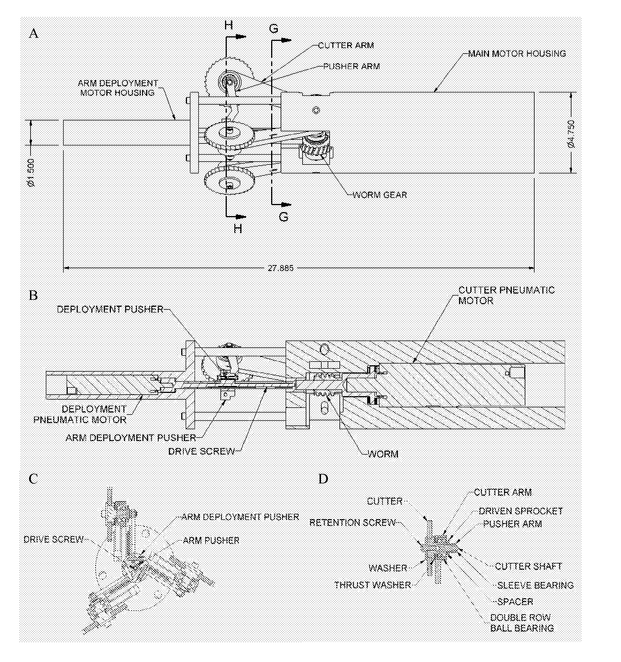
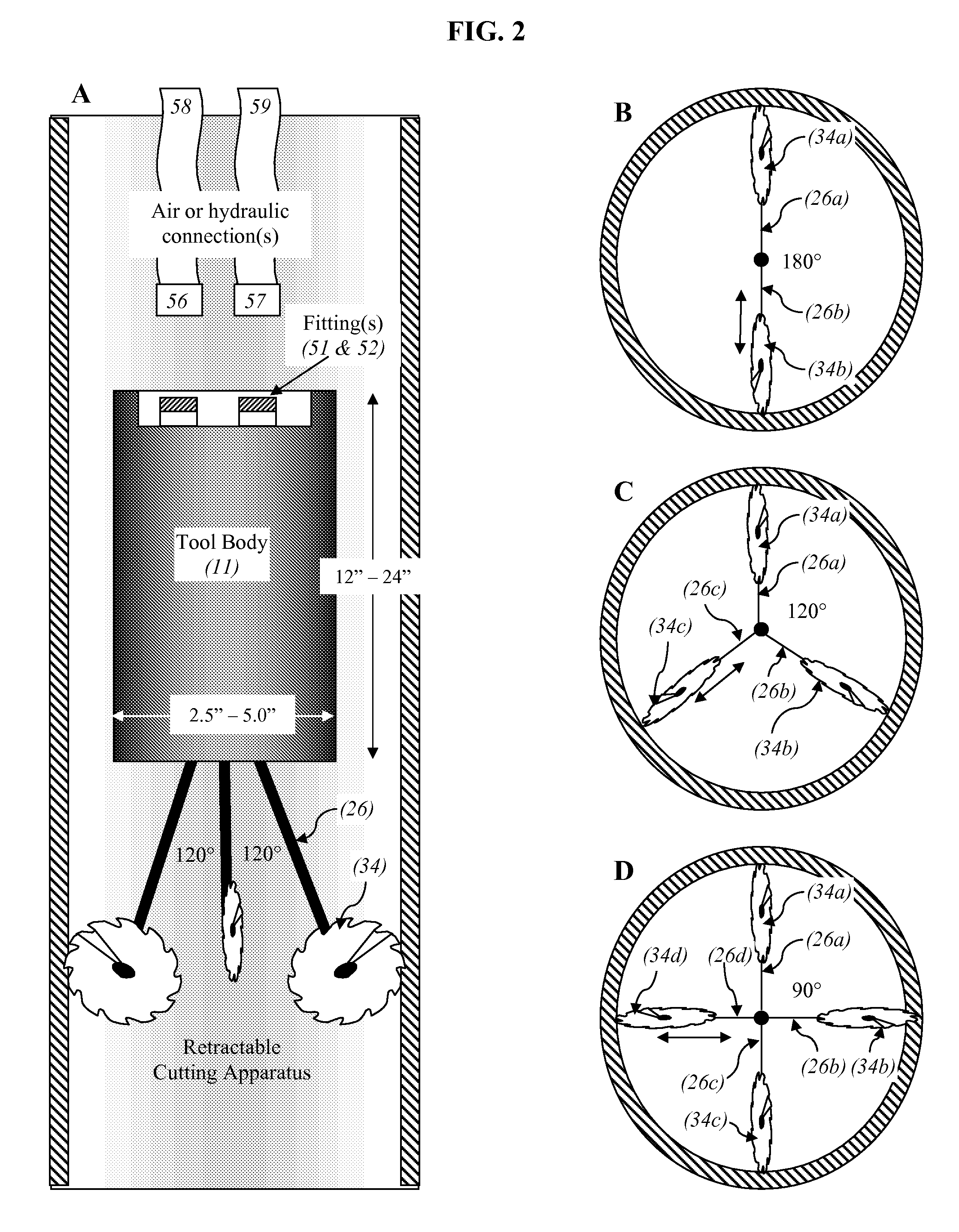
[0030]In one embodiment an airtool was designed to cut ¼″ slots in a 6 to 8 inch diameter pipe. The tool including housing, motor, cutters, pusher motor and housing, is approximately 28″ in overall length and about 4¾ inches in overall diameter. The cutting wheels are shown in their fully deployed position (FIG. 4). The Cutter is held in place on the shaft with a washer and screw. A double row ball bearing is used to support the shaft. The bearing is captured in the arm by an internal shoulder in the arm and a flange on the cutter shaft. The pusher arm is also attached to the shaft to move the cutter out to the pipe ID. Cutter deployment is slowed or stopped when the arm impacts the ID of the tube and cutting begins, the arm is then extended further until a slot is cut through the pipe. A pneumatic motor or electric motor (45) may be used to deploy the arms (26). One advantage of a pneumatic motor is that stall does not hurt the motor. With an electric motor, mo...
example ii
Electric Cutter Tool
[0038]In another embodiment a sealed electric motor is used to power the internal cutter tool. Electric motors can provide drive and torque from a motor with a smaller diameter. The cutting tool can be scaled to very small diameters using electric AC or DC motors. Brushless motors can minimize the danger of spark or flames. Containing the electric motor in a sealed housing may be an added safety measure.
[0039]In one embodiment a ½ horsepower electric motor rotates a drive shaft bevel or miter gear. The drive shaft bevel or miter gear drives a second miter or bevel gear. The second gear drives a cutter arm belt that in turn rotates the cutter shaft. The cutter shaft rotates one or two cutters, thus cutting a slot or pair of slots into the riser pipe. The cutting arms may be pushed out by the main motor when the motor is activated, or may be driven by a second motor or solenoid.
example iii
Tool Operation
[0040]Methane wells may be ventilated when methane production from a given well is reduced due to clogging, flooding, pipe damage, or other factors that may make the well inoperable. A riser may also be slotted as upper waste bodies begin to produce methane, or risers may be vented in an effort to reduce total methane emissions. First, a visual inspection of the vertical pipe ensures the riser is continuous and not damaged. A video camera is run down the pipe to identify obstructions, mark depths and identify any bends in the pipe. Depths of target waste body and desired areas for slotting are then diagrammed and the amount of slotting required for waste body length is calculated. The internal slot tool is dropped or lowered down the vertical pipe (or pushed if a solid pipe, bar, or wire is attached) to the desired depth. Cutting is initiated by powering the tool and expanding the cutting apparatus to the walls of the pipe. The tool is raised a desired length while cut...
PUM
 Abstract
Description
Claims
Application Information
 - R&D
- Intellectual Property
- Life Sciences
- Materials
- Tech Scout
- Unparalleled Data Quality
- Higher Quality Content
- 60% Fewer Hallucinations
Browse by: Latest US Patents, China's latest patents, Technical Efficacy Thesaurus, Application Domain, Technology Topic, Popular Technical Reports.
© 2025 PatSnap. All rights reserved.Legal|Privacy policy|Modern Slavery Act Transparency Statement|Sitemap|About US| Contact US: help@patsnap.com


