[0008]The inventive method serves to operate a wind energy
plant with a doubly-fed asynchronous machine, the wind energy plant comprising grid-sided and a generator-sided converter. Preferably, the converters are connected by a
direct current link. Further, according to the invention, there is provided a control means controlling the converters. The inventive method in the regular operating mode comprises the step that the converters of the wind energy plant are controlled by the control means by means of command variables. According to the invention, in case of fault, the converters are controlled by at least one control module, which controls the torque and / or the active power and the reactive current and / or the reactive power by means of command variables such that a disconnection of the asynchronous machine from the network will be performed only if the
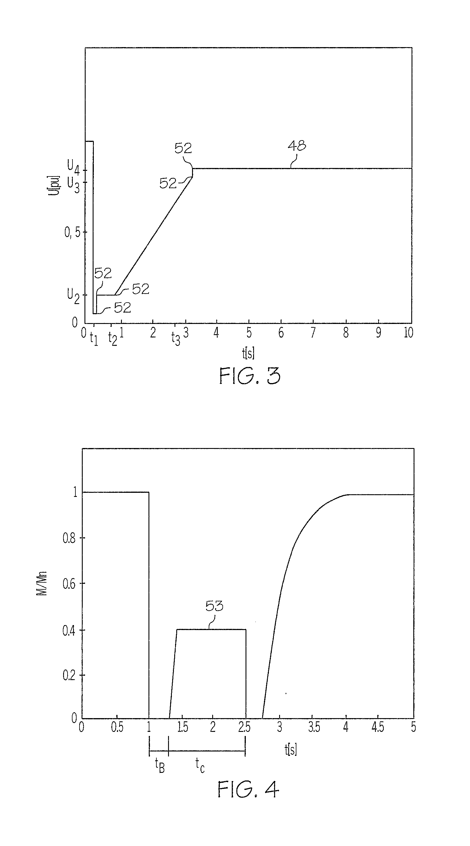
grid voltage falls below a predetermined voltage-time-characteristic curve. According to the invention, the shape of the voltage-time-characteristic curve is determined by a plurality of pre-selectable parameters in the at least one control module. In the inventive method, in addition to the conventional control means which controls the feed-in into the grid in a way known as such, there is provided at least one control module which in the case of fault completely takes over the control of the converters by means of command variables in order to comply with the FRT-requirements of the
grid code. When there is a change of the grid requirements, the
advantage of such a modular control of the wind energy plant is that, starting from the control in the regular operating mode, it is no longer necessary to re-engineer the entire control, but only to adapt one or a plurality of control modules for the case of fault. By means of the voltage-time-characteristic curve being parameterizable, it is made sure that the at least one control module for the
adaptation to different FRT-requirements can easily be adapted by a suitable selection of the parameters. All in all, using a modular, parameterizable control allows to apply the control modules following a parameterization without interfering with the control processes. In this way, the development times and the necessary change-over times for a change in the FRT-requirements can be reduced considerably.
[0009]According to a preferred aspect of the inventive method, at least one command variable function for the reactive current and / or the reactive power is retained in the at least one control module. The command variable function in the case of fault provides a command variable for the control of at least one converter. It is preferred as well to retain in the at least one control module at least one command variable function which in the case of fault provides a command variable for the torque and / or the active power. In the case of fault, the command variable function in the control module allows to provide the command variables for the control in the converter. The control of the converters is performed in the regular operating mode as well as in the case of fault by means of the command variables, so that there is no
structural difference for the converters regarding their control.
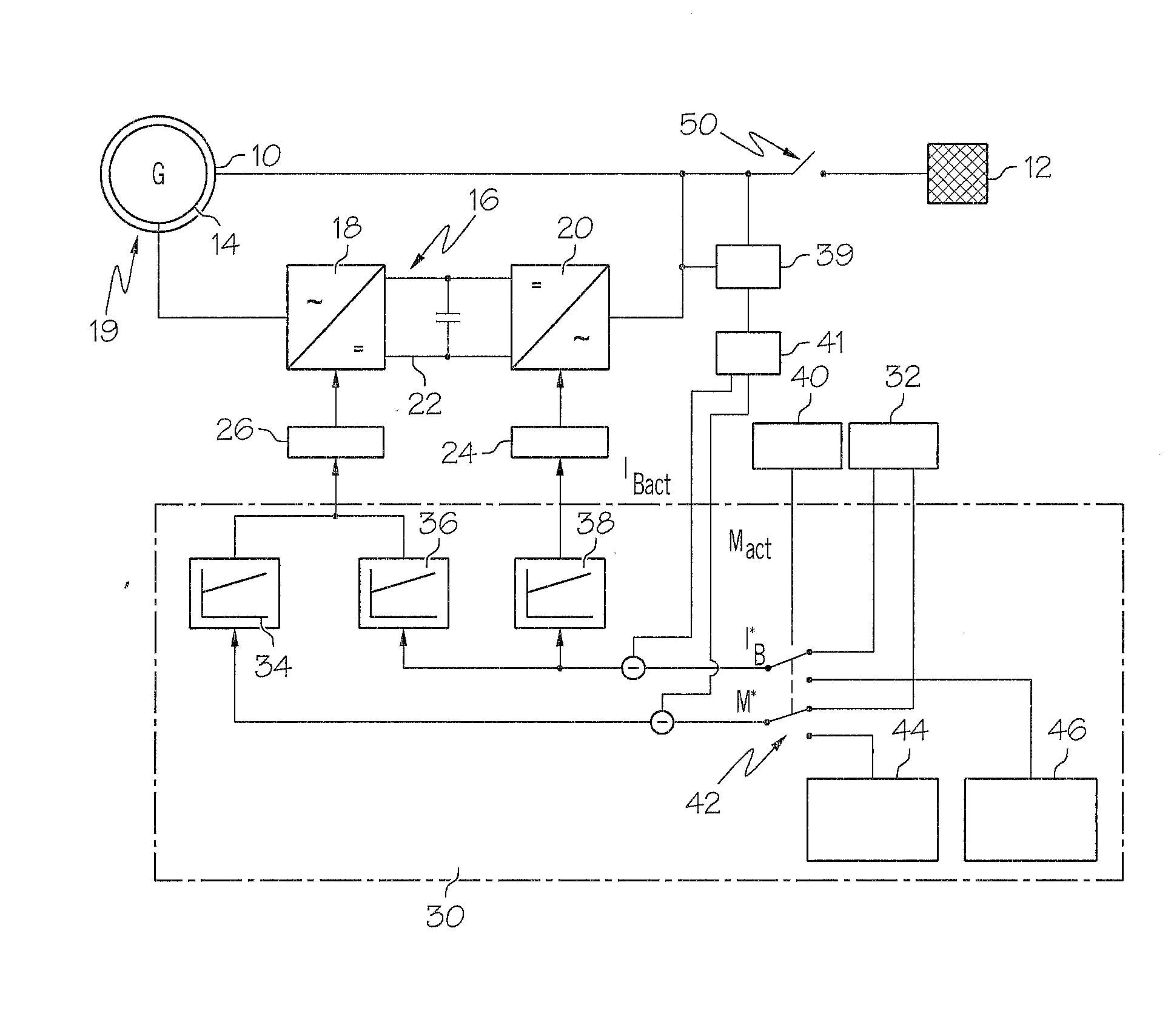
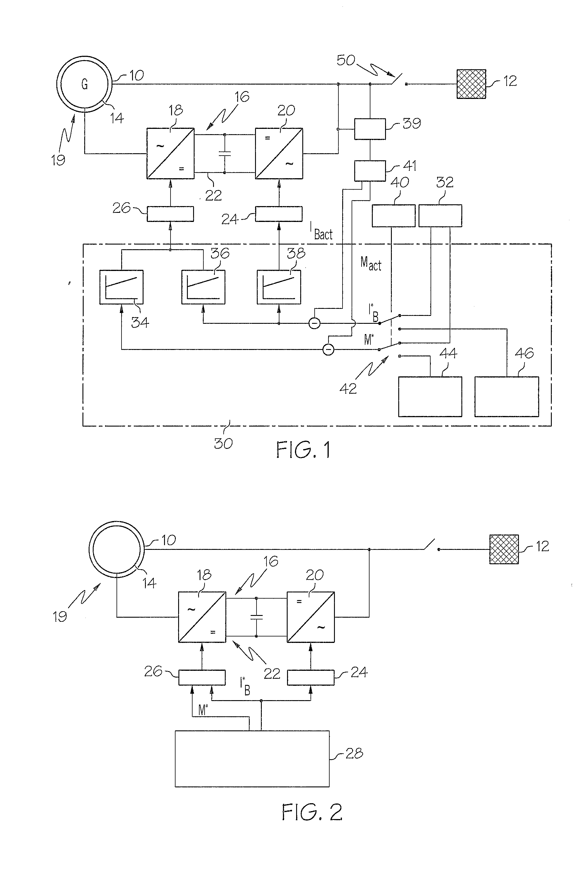
[0012]According to a preferred aspect, in the case of fault the first control module provides a
set point for a reactive current IB to be generated to at least one converter. Preferably, the second control module in the case of fault provides a
set point for the torque and / or an active power to the generator-sided converter. By using two control modules, it is possible not only to design the control of the wind energy plant in a modular and parameterizable manner, but by way of distinguishing between a torque function and a
current function, the control can also be easily adjusted to the design of the wind energy plant, that is for example to the rotor used, the power
train, and further
mechanical components.
[0016]Preferably, the first basic function in a first time interval reduces the torque
set point and / or active power set point preferably to a value close to zero, and in a second, subsequent time interval the set point is increased to a predetermined minimum value. Advantageously, the minimum value is defined by parameters in the control module, so that it can easily be adapted. Preferably, the set point of the first basic function is dependent on a grid voltage present in the case of fault. In a particularly preferred aspect, the dependency of the set point on the grid voltage and / or the predetermined minimum value of the first basic function is selected dependent on if a fault is present in all phases or in only one or two phases of the grid. That is, with regard to the parameters of the first basic function, it is distinguished whether a so-called symmetric fault or an asymmetric fault is present, wherein a fault in all three phases is denoted a symmetric fault and a fault affecting not all of the phases of the grid is denoted an asymmetric fault. As a result of the additional differentiation of symmetric and asymmetric faults for the use of the sets of parameters suitable to this end, the first basic function provides a large spectrum in order to easily adapt the control module to different FRT-requirements.
[0018]By using the two basic functions, the control module for the torque and / or active power set points can be adapted very easily to different voltage-time-characteristic curves.
[0020]According to the invention, the problem is also solved by a wind energy plant with a doubly-fed asynchronous machine, the wind energy plant comprising a grid-sided converter, a generator-sided converter and a control means controlling the converters by means of command variables. The control means of the invention comprises a fault detection module which triggers a control of the converters by means of at least on control module. The at least one control module controls the converters by means command variables such that a disconnection of the asynchronous machine from the grid does not happen as long as the grid voltage does not fall below a predetermined voltage-time-characteristic curve. By means of the command variables, a torque and / or an active power and a reactive current and / or a reactive power is provided to the converters. The control of the inventive wind energy plant consists of a fault detection module and at least one control module in order to react to a fault in the grid, wherein the
modular design of the control allows for an easy
adaptation to different FRT-requirements. According to the invention, the shape of the voltage-time characteristic curve is defined by pre-selectable parameters in the at least one control module. In this way, the modular control of the inventive wind energy plant can easily be re-parameterized and adjusted according to the FRT-requirements of the grid operators.

