Passive over/under voltage control and protection for energy storage devices associated with energy harvesting

a technology of over/under voltage control and energy storage devices, applied in the direction of secondary cell servicing/maintenance, electrochemical generators, safety/protection circuits, etc., can solve the problems of battery damage, battery discharge beyond the design parameters, and energy storage devices such as capacitors may be susceptible to damage, etc., to achieve the effect of safe connection

Active Publication Date: 2009-10-08
SAPURAST RES
View PDF104 Cites 42 Cited by
  • Summary
  • Abstract
  • Description
  • Claims
  • Application Information

AI Technical Summary

Benefits of technology

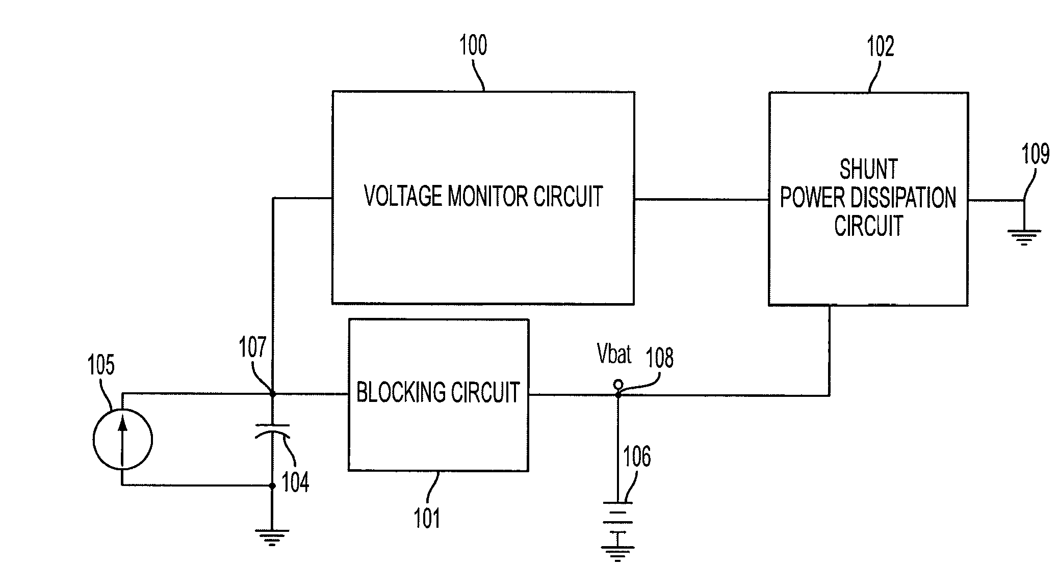
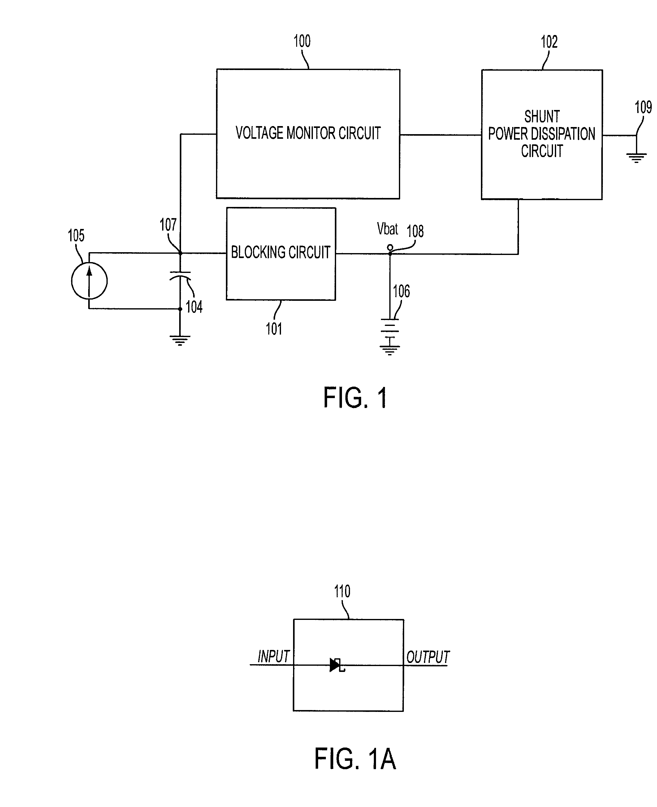
[0014]As some energy storage devices, such as, for example, thin-film solid electrolyte batteries, are sensitive to continuous or momentary influxes of high charging voltages, the over-charge and/or under-voltage circuitry may be especially useful in recharging the batteries in a safe manner. This may be particularly important, for example, in applications where energy storage devices are located in remote areas that require high reliability—the energy-harvesting system described above may recharge the energy storage devices and the over-charge and/or over-discharge circuitry may ensure that the energy storage device is not damaged by the excess and/or inadequate conditions of the charging voltage or load demand.
[0015]Certain embodiments of the present invention may...

Problems solved by technology

Some energy storage devices such as, for example, thin-film solid electrolyte batteries or capacitors may be susceptible to damage when exposed to continuous or momentary influxes of high charging voltages.
Batteries may, for example, be damaged if discharged beyond their design parameters.
Under-voltage conditions also have the potential to damage the energy storage device.
To implement the fu...

Method used


Image

  • Passive over/under voltage control and protection for energy storage devices associated with energy harvesting
  • Passive over/under voltage control and protection for energy storage devices associated with energy harvesting
  • Passive over/under voltage control and protection for energy storage devices associated with energy harvesting

Examples


Embodiment Construction

[0033]These and other aspects of the invention will now be described in greater detail in connection with exemplary embodiments that are illustrated in the accompanying drawings.

[0034]It is to be understood that the present invention is not limited to the particular methodology, compounds, materials, manufacturing techniques, uses, and applications described herein, as these may vary. It is also to be understood that the terminology used herein is used for the purpose of describing particular embodiments only, and is not intended to limit the scope of the present invention. It must be noted that as used herein and in the appended claims, the singular forms “a,”“an,” and “the” include the plural reference unless the context clearly dictates otherwise. Thus, for example, a reference to “an element” is a reference to one or more elements and includes equivalents thereof known to those skilled in the art. Similarly, for another example, a reference to “a step” or “a means” is a referenc...


PUM


Abstract

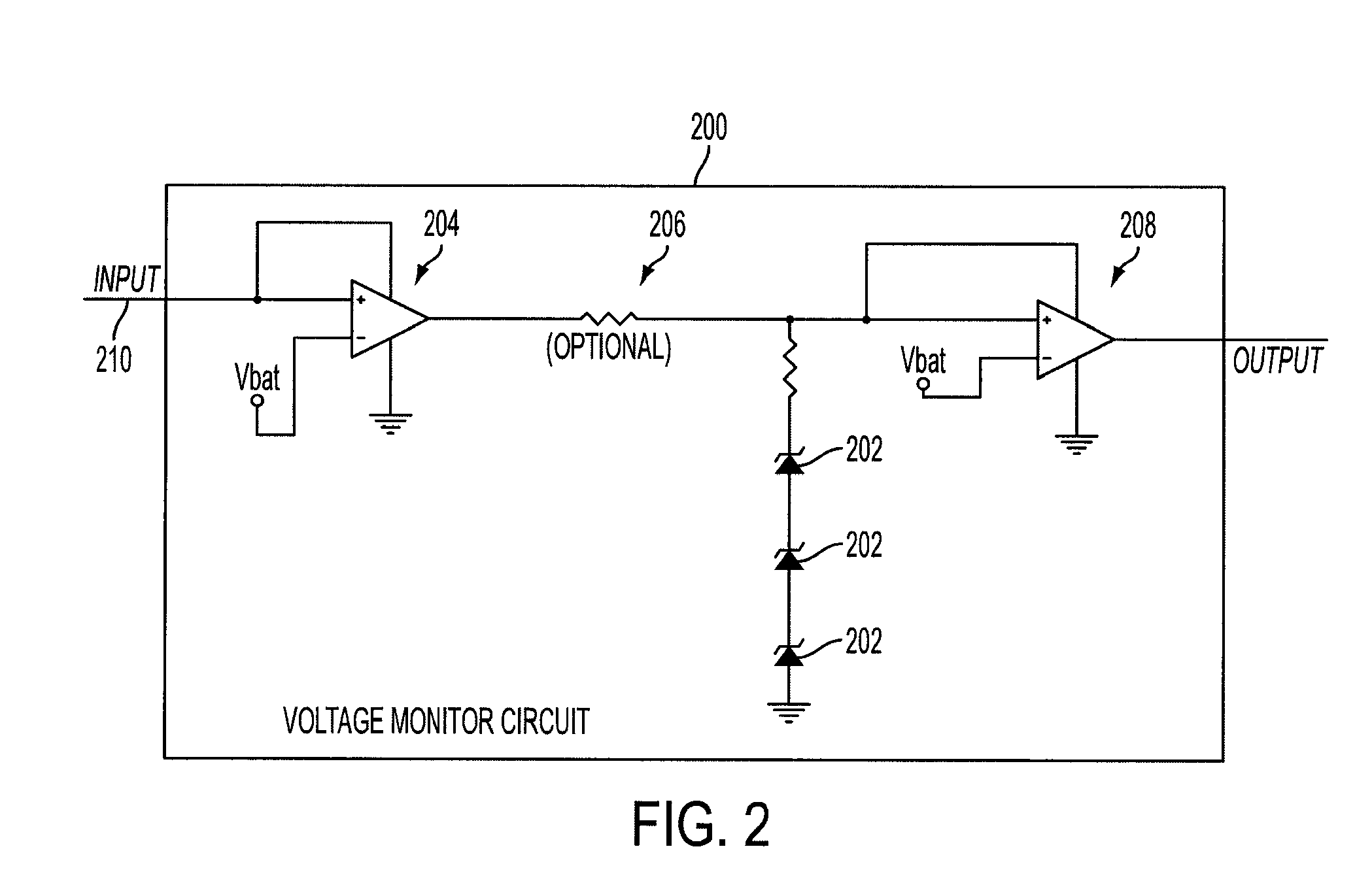
Described herein is, for example, a battery or capacitor over voltage (overcharge) and under-voltage protection circuit, that, for example, is adapted to not draw current from the battery or capacitor to be charged unless charge energy is detected and to not charge an energy storage device when an over-charge condition is sensed. The protection circuit may, for example, not be turned on unless an over voltage condition is present. Incoming energy to the system can be shunted to ground via a shunt load of various types including resistive loads and active components such as a zener diode. In some embodiments, no switching of the inbound power is required. Within limits, no regulation of inbound power is needed. When inbound power is sufficient to charge the battery or capacitor, regulation can occur via the applied shunt regulator if overcharge voltage conditions exist. Either type of charge source, voltage or current, can be used to provide charge energy. Combining said battery or capacitor over voltage (overcharge) and under-voltage protection circuit with electronic loads, such as wireless sensors, may lead to autonomously-powered wireless sensor systems.

Description

RELATED APPLICATIONS[0001]This application is related to and claims the benefit under 35 U.S.C. §119 of U.S. provisional patent application Ser. No. 61 / 103,746, entitled “Environmentally-Powered Wireless Sensor Module,” filed on Oct. 8, 2008 and U.S. provisional patent application Ser. No. 61 / 041,841, entitled “Passive Battery or Capacitor Overvoltage Control and Protection Circuit,” filed on Apr. 2, 2008; both of which are incorporated herein by reference in their entirety.TECHNICAL FIELD AND BACKGROUND OF THE INVENTION[0002]This invention relates to, for example, an apparatus, method, and system for safely utilizing a rechargeable energy device.[0003]Some energy storage devices such as, for example, thin-film solid electrolyte batteries or capacitors may be susceptible to damage when exposed to continuous or momentary influxes of high charging voltages. Batteries may, for example, be damaged if discharged beyond their design parameters.[0004]Over-charge protection relates to a con...

Claims


Application Information

Patent Timeline
IPC IPC(8): H02J7/00H02J7/04H02J7/06
CPCH02J7/0032H02J2007/004H02J2007/0037H02J7/00302H02J7/00306H02J7/00308H02J7/04
Inventor BRANTNER, PAUL C.KEATING, JOSEPH A.JOHNSON, RAYMOND R.BRADOW, TIMOTHY N.NARAYAN, PRATIVADI B.NEUDECKER, BREND J.
Owner SAPURAST RES
Why Eureka
Try Eureka