Inductors and methods of operating inductors

a technology of inductors and inductors, applied in the field of electric devices, can solve the problems of many problems in manufacturing inductors, small inductors/transformers, and low quality factor of cu inductors, so as to increase the electrical resistance of the conductive line, increase the magnitude of the electric field, and reduce the electrical resistance of the material

Inactive Publication Date: 2009-10-08
SAMSUNG ELECTRONICS CO LTD
View PDF8 Cites 15 Cited by
  • Summary
  • Abstract
  • Description
  • Claims
  • Application Information

AI Technical Summary

Benefits of technology

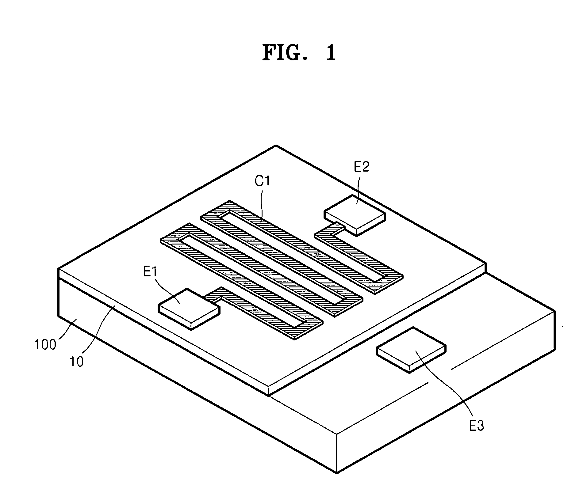
[0019]According to example embodiments, increasing a magnitude of the electric field may increase the electrical resistance of the material. In addition or in the alternative, increasing the magnitude of the electric field may decrease an electrical resistance of the conductive line. In addition or in the alternative, increasing the magnitude of the electric field may decrease a quality factor of the inductor.

Problems solved by technology

However, it may be difficult to make the inductors small and / or have a high performance as compared to other passive devices, such as capacitors or resistors.
In the case of a copper (Cu) inductor, even if the Cu inductor may have a line width of about several μm, the resistance of the Cu inductor may increase relative to self-inductance of the Cu inductor, and thereby, may decrease a quality factor of the Cu inductor.
When an inductor is manufactured using a carbon nanotube (CNT), there may be many problems in manufacturing the inductor.
For example, it may be difficult to ensure uniformity and / or reproductivity during a CNT composition process and / or to arrange the composited CNT in a desired position of a substrate.
Accordingly, it may be difficult to apply a CNT inductor to a real circuit.
On the other hand, in the case of an inductor using an operational amplifier, the structure of the inductor may be complicated, and thus it may be difficult to form the inductor.
In addition or in the alternative, increasing the magnitude of the electric field may decrease an electrical resistance of the conductive line.
In addition or in the alternative, increasing the magnitude of the electric field may decrease a quality factor of the inductor.

Method used


Image

  • Inductors and methods of operating inductors
  • Inductors and methods of operating inductors
  • Inductors and methods of operating inductors

Examples


Embodiment Construction

[0032]Example embodiments will now be described more fully with reference to the accompanying drawings. Embodiments, however, may be embodied in many different forms and should not be construed as being limited to the embodiments set forth herein. Rather, these example embodiments are provided so that this disclosure will be thorough and complete, and will fully convey the scope to those skilled in the art. In the drawings, the thicknesses of layers and regions are exaggerated for clarity.

[0033]It will be understood that when an element is referred to as being “on,”“connected to,”“electrically connected to,” or “coupled to” to another component, it may be directly on, connected to, electrically connected to, or coupled to the other component or intervening components may be present. In contrast, when a component is referred to as being “directly on,”“directly connected to,”“directly electrically connected to,” or “directly coupled to” another component, there are no intervening comp...


PUM

PropertyMeasurementUnit
widthaaaaaaaaaa
electrical resistanceaaaaaaaaaa
capacitanceaaaaaaaaaa

Abstract

An inductor may include a conductive line including a material in which an electrical resistance varies depending on an electric field applied to the material and / or first and second electrodes electrically connected to first and second end portions of the conductive line, respectively. A method of operating an inductor may include applying current to a conductive line of the inductor. The conductive line may include a material in which an electrical resistance may vary depending on an electric field applied to the material. The current may be applied to the conductive line via first and second electrodes electrically connected to first and second end portions of the conductive line, respectively.

Description

PRIORITY STATEMENT[0001]This application claims priority from Korean Patent Application No. 10-2008-0031714, filed on Apr. 4, 2008, in the Korean Intellectual Property Office (KIPO), the entire contents of which are incorporated herein by reference.BACKGROUND[0002]1. Field[0003]Example embodiments relate to electric devices. Also, example embodiments relate to inductors and methods of operating the same.[0004]2. Description of Related Art[0005]Inductors are a kind of passive device and are important devices in most electronic circuits. In particular, in radio frequency (RF) application circuits, in addition to capacitors, inductors are used in almost all filters.[0006]As such, inductors may be used in most electronic circuits, and thus, the inductors may need to be small in order to obtain highly integrated circuits. However, it may be difficult to make the inductors small and / or have a high performance as compared to other passive devices, such as capacitors or resistors.[0007]In t...

Claims


Application Information

Patent Timeline
Patent Type & Authority Applications(United States)
IPC IPC(8): H01F5/00
CPCH01F17/0006H01F21/005H03H2001/0092H01F27/34H01F41/045H01F21/02H01F2017/0073H01F27/00
Inventor JEON, DAE-YOUNGKIM, DONG-CHULSEO, SUN AEJUNG, RAN-JUWOO, YUN-SUNGCHUNG, HYUN-JONG
Owner SAMSUNG ELECTRONICS CO LTD
Why Eureka
Try Eureka