Cladding pumped fibre laser with a high degree of pump isolation

Active Publication Date: 2009-10-08
SPI LASERS UK
View PDF22 Cites 16 Cited by
  • Summary
  • Abstract
  • Description
  • Claims
  • Application Information

AI Technical Summary

Benefits of technology

[0017]According to the present invention there is provided an optical fibre laser or amplifier device, comprising: a rare-earth-doped multi-clad optical fibre having at least three cladding layers, one or more multimode pump laser diodes, and a means of multiplexing a laser signal and the pumping radiation, adapted so that a fraction of the stray signal light originating within the device is captured by one of the intermediate cladding layers of the rare-earth-doped fibre and guided out of the laser structure through the multiplexing system resulting in a reduction in the amount of stray signal radiation impinging upon the pump laser diodes.
[0018]In a further aspect, the invent

Problems solved by technology

Such problems may be diode damage or spurious outputs from

Method used


Image

  • Cladding pumped fibre laser with a high degree of pump isolation
  • Cladding pumped fibre laser with a high degree of pump isolation
  • Cladding pumped fibre laser with a high degree of pump isolation

Examples


Embodiment Construction

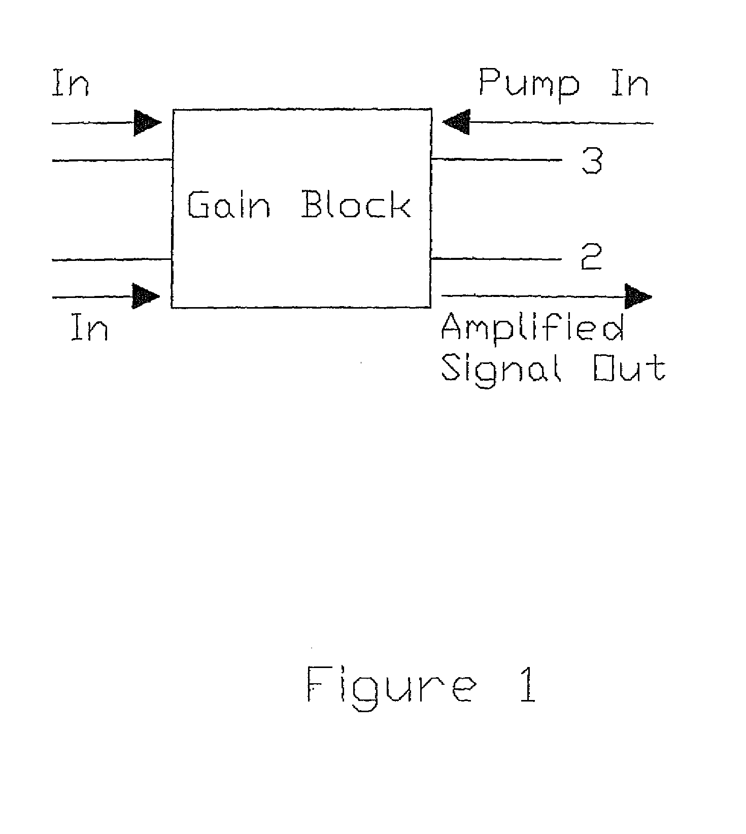
[0041]A cladding-pumped fibre laser typically includes an optical sub-system shown as gain block in FIG. 1. The function of this gain block, as illustrated in FIG. 1, is to amplify an optical signal. The energy required by the gain block to amplify the signal is provided in the form of optical pumping radiation. Typically the gain block has two ends; the signal is coupled into the gain block via an optical fibre input at the first end, poll 1, and the amplified signal exits the gain block via another optical fibre at the second end, port 2; the pumping radiation may be coupled into the gain block from one or both ends via optical fibre inputs, ports 3 and 4. The gain block may operate hi-directionally with signals propagating in both directions through the device simultaneously or with external signal feedback to form a laser.

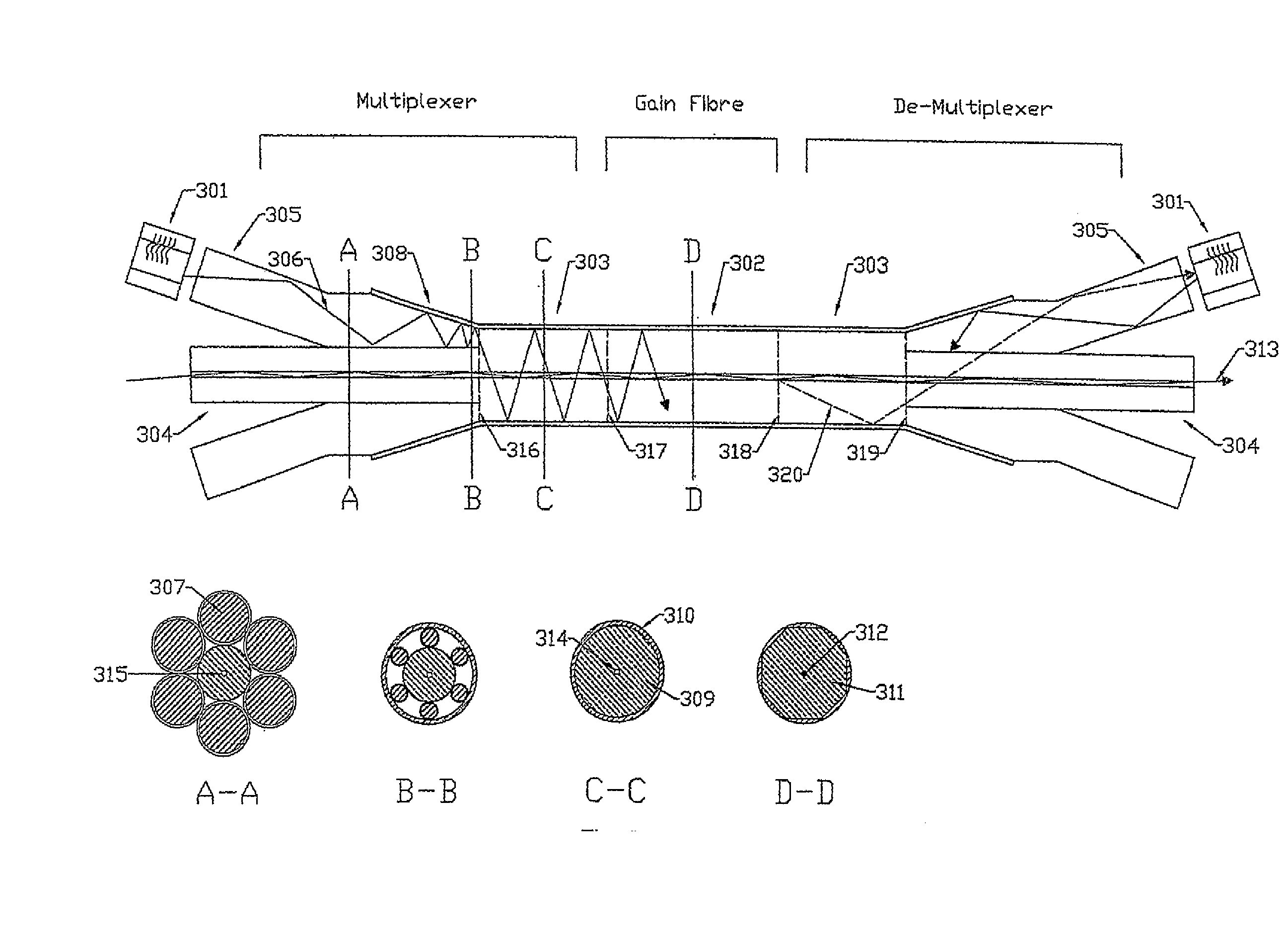
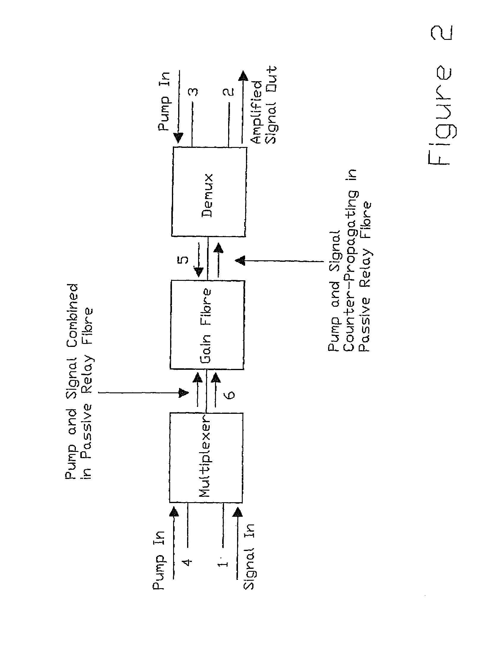
[0042]FIG. 2 shows a block diagram illustrating the main elements of the gain block. These are the multiplexer, the gain fibre, and the dc-multiplexer. Section...


PUM


Abstract

An optical fibre laser or amplifier device is disclosed, comprising: a rare-earth-doped multi-clad optical fibre having at least three cladding layers, one or more multimode pump laser diodes, and a means of multiplexing a laser signal and the pumping radiation, adapted so that a fraction of the stray signal light originating within the device is captured by one of the intermediate cladding layers of the rare-earth-doped fibre and guided out of the laser structure through the multiplexing system resulting in a reduction in the amount of stray signal radiation impinging upon the pump laser diodes.
Alternatively the device may have a rare-earth-doped multi-clad optical fibre having at least two cladding layers, one or more passive multi-clad optical fibres having at least three cladding layers, one or more multimode pump laser diodes, and a means of multiplexing a laser signal and the pumping radiation, adapted so that a fraction of the stray signal light originating within the device is captured by one of the intermediate cladding layers of the passive multi-clad fibre and guided out of the laser structure through the multiplexing system resulting in a reduction in the amount of stray signal radiation impinging upon the pump laser diodes. Other variations and embodiments are disclosed.

Description

BACKGROUND OF THE INVENTION[0001]Cladding pumped fibre lasers are becoming well-known. A core of an optical fibre is doped with a rare earth element to become an active gain medium and pump radiation is applied via a cladding layer. The pump radiation is normally produced by a plurality of semiconductor laser diodes, and a means is provided for coupling their output into the cladding of the rare earth doped fibre. Bragg gratings formed in the core of the optical fibre may be employed as mirrors to form a laser cavity.[0002]Some pump diodes are sensitive to optical feedback from the laser and can be damaged, particularly if the laser is operating in a pulsed mode. In general, the amount of feedback experienced by the pump diodes depends upon the means of coupling between the pump diodes and the cladding pumped fibre. This invention is a cladding pumped fibre laser structure that has improved confinement of the laser signal to the core region and a lower level of optical feedback to t...

Claims


Application Information

Patent Timeline
IPC IPC(8): H01S3/00
CPCG02B6/03633G02B6/03638G02B6/03688G02B6/2804H01S3/06729H01S3/09415H01S3/0675H01S3/06754H01S3/094007H01S3/094011H01S3/094019H01S3/06745H01S3/063H01S3/067H01S3/06708
Inventor LEWIS, STEFFAN
Owner SPI LASERS UK
Why Eureka
Try Eureka