
Exposure method and exposure device

Active Publication Date: 2009-10-08
SHARP KK
View PDF4 Cites 7 Cited by
  • Summary
  • Abstract
  • Description
  • Claims
  • Application Information

AI Technical Summary

Benefits of technology

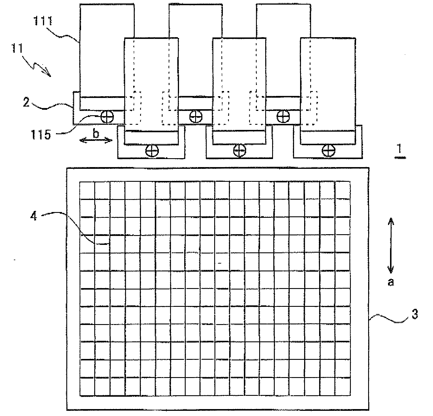
[0011]An object of the invention is to overcome the problems described above and to provide a method for performing exposure by projecting ultraviolet light or other light onto some regions on a surface of a substrate using a plurality of small photomasks having slit openings while moving the substrate. This method enables predetermined regions on the substrate surface to be exposed in stripes (i.e. irradiated with ultraviolet light or other light). In addition, while projecting ultraviolet light or other light and moving the substrate, this method simultaneously photographs existing patterns prearranged on the substrate surface, for example, line patterns including gate bus lines, source bus lines, and a black matrix, and a reference mark arranged on the photomask, in order to monitor the position onto which the light is actually projected, that is, the position of the photomask with respect to the existing patterns using a photographed image. By such exposure method, it is possible to perform exposure with high alignment accuracy regardless of the sizes of substrates.
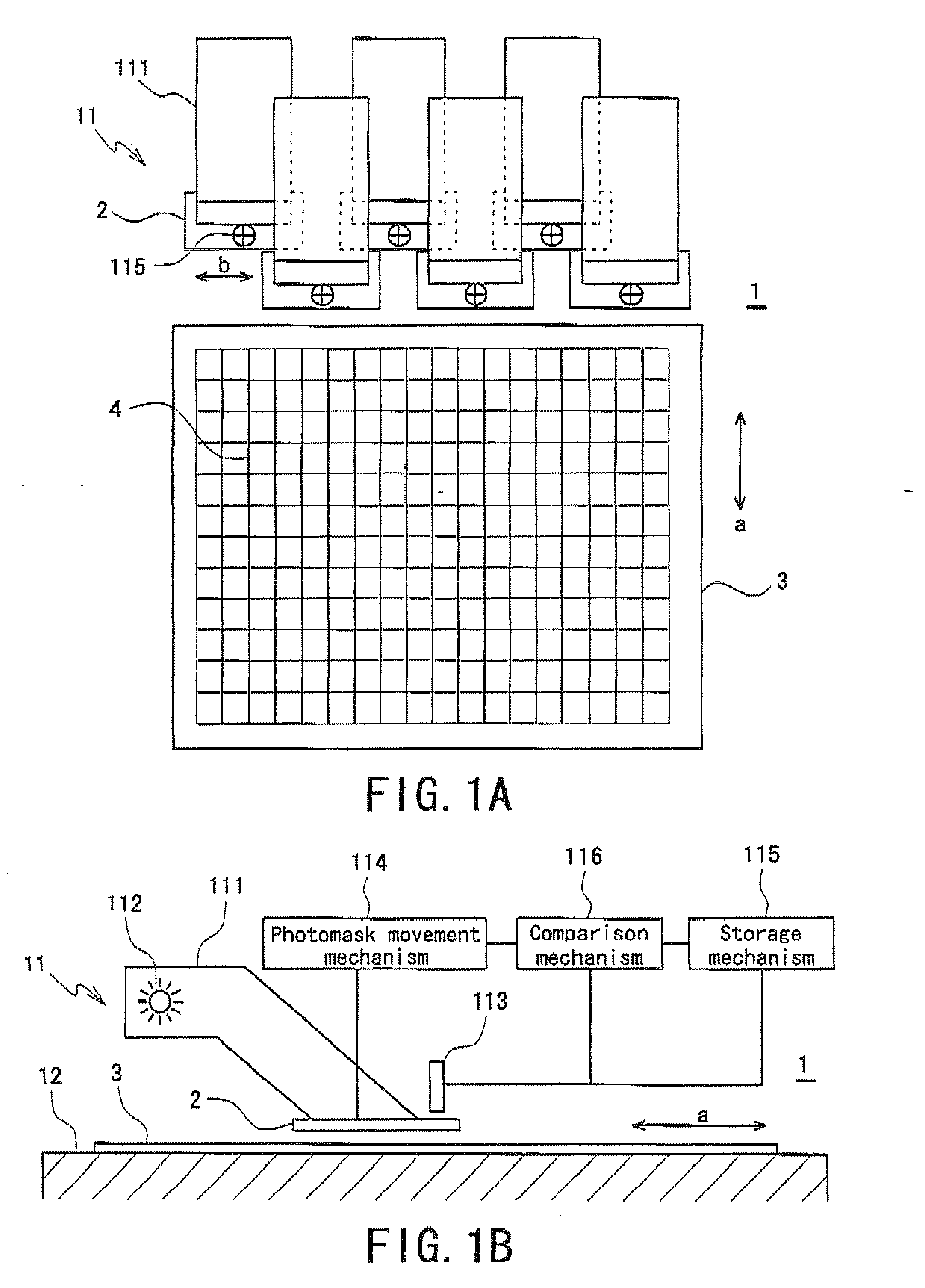
[0012]Preferred embodiments of the present invention provides an exposure method which performs exposure while relatively moving a photomask above a substrate and includes a step of performing position correction of a photomask by performing, on a front side of the photomask relatively moved in a moving direction, image recognition of a pattern prearranged on the substrate and by correcting deviation of the photomask with respect to the pattern, and a step of checking the position correction of the photomask by performing image recognition of a reference mark arranged on the photomask and by determining whether or not the position correction of the photomask is accurately performed in the step of performing the position correction of the photomask.
[0015]Preferred embodiments of the present invention also provide an exposure device which performs exposure while relatively moving a photomask above a substrate and includes a mechanism to perform position correction of the photomask by performing, on a front side of the photomask relatively moved in a moving direction, image recognition of a pattern prearranged on the substrate and by correcting deviation of the photomask with respect to the pattern, and a mechanism to check the position correction of the photomask by performing image recognition of a reference mark arranged on the photomask and by determining whether or not the position correction of the photomask is accurately performed by the mechanism to perform the position correction of the photomask.
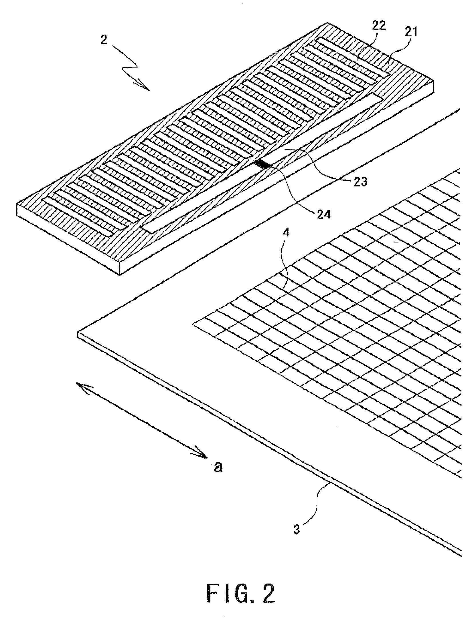
[0019]If the photomask is configured such that the light transmitting window for performing the image recognition of the pattern prearranged on the substrate is arranged on the photomask and the reference mark of the photomask is arranged on the light transmitting window, the light transmitting window and the reference mark can be provided in a normal manufacturing process of the photomask. Accordingly, the cost to manufacture the photomask does not increase.
[0020]In addition, if the image recognition of the pattern prearranged on the substrate and the image recognition of the reference mark of the photomask are performed using one camera, it becomes possible to simplify equipment for the image recognition, and the positioning accuracy of the camera is improved as compared to the case of providing two cameras for both of the image recognitions.
[0021]Further, if the camera is a bifocal camera, it is possible to simultaneously perform focus adjustment in the image recognition of the pattern prearranged on the substrate and focus adjustment in the image recognition of the reference mark of the photomask. Thus, recognized images are not blurred, thereby allowing easier image processing such as detection of edges.

Problems solved by technology

If deviation in an exposure position and / or an exposure range occurs, conditions such as of alignment of liquid crystals and of lines arranged on the substrate may become different from the designed conditions, causing the substrate to fail to have designed alignment or characteristics.
For example, if deviation in a position and / or a range of light energy projection occurs in the exposure step to provide the photoalignment process to the alignment layer, it becomes impossible to provide the designed pretilt angle to the liquid crystals.
In addition, when projecting light energy onto the surface to be irradiated of the substrate using a photomask, the accuracy regarding the position and / or the range of light energy projection is significantly influenced by the dimensional accuracy of a pattern of light shielding portions and light transmitting portions which are arranged on the photomask, thereby rendering the photomask to be expensive.
Moreover, the size of photomasks has been increased along with recent upsizing of substrates, resulting in even more expensive photomasks.
Further, when a large photomask is used, problems tend to occur such as change in the sizes of light shielding portions and light transmitting portions and deviation in alignment with the substrate, due to factors such as deformation and thermal expansion.
Countermeasures against the problems are performed for example by suppressing the change in the sizes by managing the temperatures of the substrate and the photomask and by improving the accuracy of the mechanism for alignment and the control thereof, but such countermeasures result in complicated processes and increased running costs.

Method used


Image

  • Exposure method and exposure device
  • Exposure method and exposure device
  • Exposure method and exposure device

Examples


Embodiment Construction

[0028]A detailed description of preferred embodiments of the present invention will now be given with reference to the accompanying drawings. FIGS. 1A and 1B are schematic views illustrating a configuration of major portions of an exposure device according to a preferred embodiment of the present invention, and FIG. 1A is an overhead view of the exposure device seen from above a surface to be irradiated of a substrate, while FIG. 1B is a side view of the exposure device.

[0029]An exposure device 1 includes a plurality of exposure units 11 which project light energy onto a surface to be irradiated of a substrate 3, and a table 12 which supports and moves the substrate 3. Arrows a in FIGS. 1A and 1B indicate the moving direction of the substrate 3 on the table 12.

[0030]Each of the exposure units 11 has an exposure head 111, a light source 112, a photomask 2, a camera 113, a photomask movement mechanism 114, a storage mechanism 115, and a comparison mechanism 116. By arranging a plurali...


PUM


Abstract

An exposure method capable of performing accurate exposure without using a large photomask. The exposure method performs exposure while relatively moving a photomask above a substrate and includes a step of performing position correction of the photomask by performing, on a front side of the photomask relatively moved in a moving direction, image recognition of a pattern prearranged on the substrate such as a line and a black matrix and by correcting deviation of the photomask with respect to the pattern, and a step of checking the position correction of the photomask by performing image recognition of a reference mark arranged on the photomask and by determining whether or not the position correction of the photomask is accurately performed in the step of performing the position correction of the photomask.

Description

BACKGROUND OF THE INVENTION[0001]1. Field of the Invention[0002]The present invention relates to an exposure method and an exposure device, and in particular relates to an exposure method and an exposure device which perform exposure while relatively moving a substrate and a photomask.[0003]2. Description of the Related Art[0004]In a liquid crystal display panel, a pair of substrates are arranged opposing to each other at a predetermined gap, and liquid crystals are filled therebetween. On one of the substrates, constituents are stacked such as pixel electrodes which apply voltage Lao the liquid crystals, switching elements such as thin film transistors which drive the pixel electrodes, various lines such as gate bus lines and source bus lines, and an alignment layer which provides a pretilt angle to the liquid crystals. On the other substrate, constituents are stacked such as a black matrix, color filter layers having predetermined colors, common electrodes, and an alignment layer....

Claims


Application Information

Patent Timeline
IPC IPC(8): G06K9/62G03F7/20
CPCG03F7/7035G03F9/7088G03F9/7003G03F7/70791
Inventor OGATA, SHOUICHIFUSE, DAISUKEMINAMI, YASUO
Owner SHARP KK
Features
  • Generate Ideas
  • Intellectual Property
  • Life Sciences
  • Materials
  • Tech Scout
  • Unparalleled Data Quality
  • Higher Quality Content
  • 60% Fewer Hallucinations
Learn More