Optical path changing member

a technology of optical path and optical fiber, applied in the field of optical path changing member, can solve the problems of product yield decline, difficulty in positioning optical fibers and forming lenses with high accuracy, etc., and achieve the effects of reducing the loss of light propagation, high accuracy, and increasing the defective occurrence ra

Active Publication Date: 2009-10-08
THE FUJIKURA CABLE WORKS LTD
View PDF10 Cites 59 Cited by
  • Summary
  • Abstract
  • Description
  • Claims
  • Application Information

AI Technical Summary

Benefits of technology

[0010]The present invention has been made in view of the aforementioned circumstances, and an object of the present invention is to provide an internal-reflection optical path changing member in which optical fibers can be easily positioned in a member body with high accuracy, and which therefore has stable optical interconnection characteristics and high product yield.
[0031]Also, smoothing a surface of a mold of upward releasing type for molding the inner wall makes it easy to mold the inner wall of with high accuracy, the optical fibers coming into contact with the end placement portion for positioning thereof.
[0032]The inner wall which is an accurately-smoothed surface can reduce the loss of light propagating between the optical fibers and the inner wall.
[0034]Since it is easy to bond optical fibers to optical fiber insertion holes with both ends open, with an adhesive, the product yield of the present invention is less likely to decrease.
[0035]Further, the ends of the optical fibers can be fixed in the end placement portion by embedding the ends of the optical fibers in the adhesive. Thus, stable optical interconnection can be established.
[0036]Moreover, in the end placement portion, air bubbles are easily released from the adhesive. This can prevent residual air bubbles from adversely affecting the optical interconnection.

Problems solved by technology

However, since end faces of the optical fibers are placed at the end face of the optical coupling element, it is difficult to position the optical fibers and form the lenses with high accuracy.
Thus, product yield tends to decrease.

Method used


Image

  • Optical path changing member
  • Optical path changing member
  • Optical path changing member

Examples


Embodiment Construction

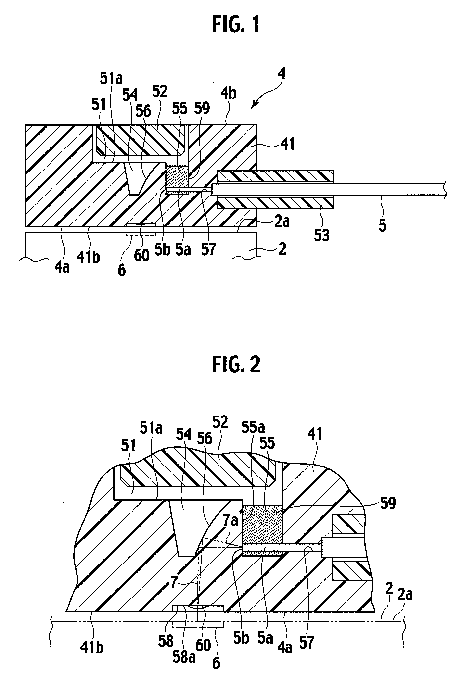
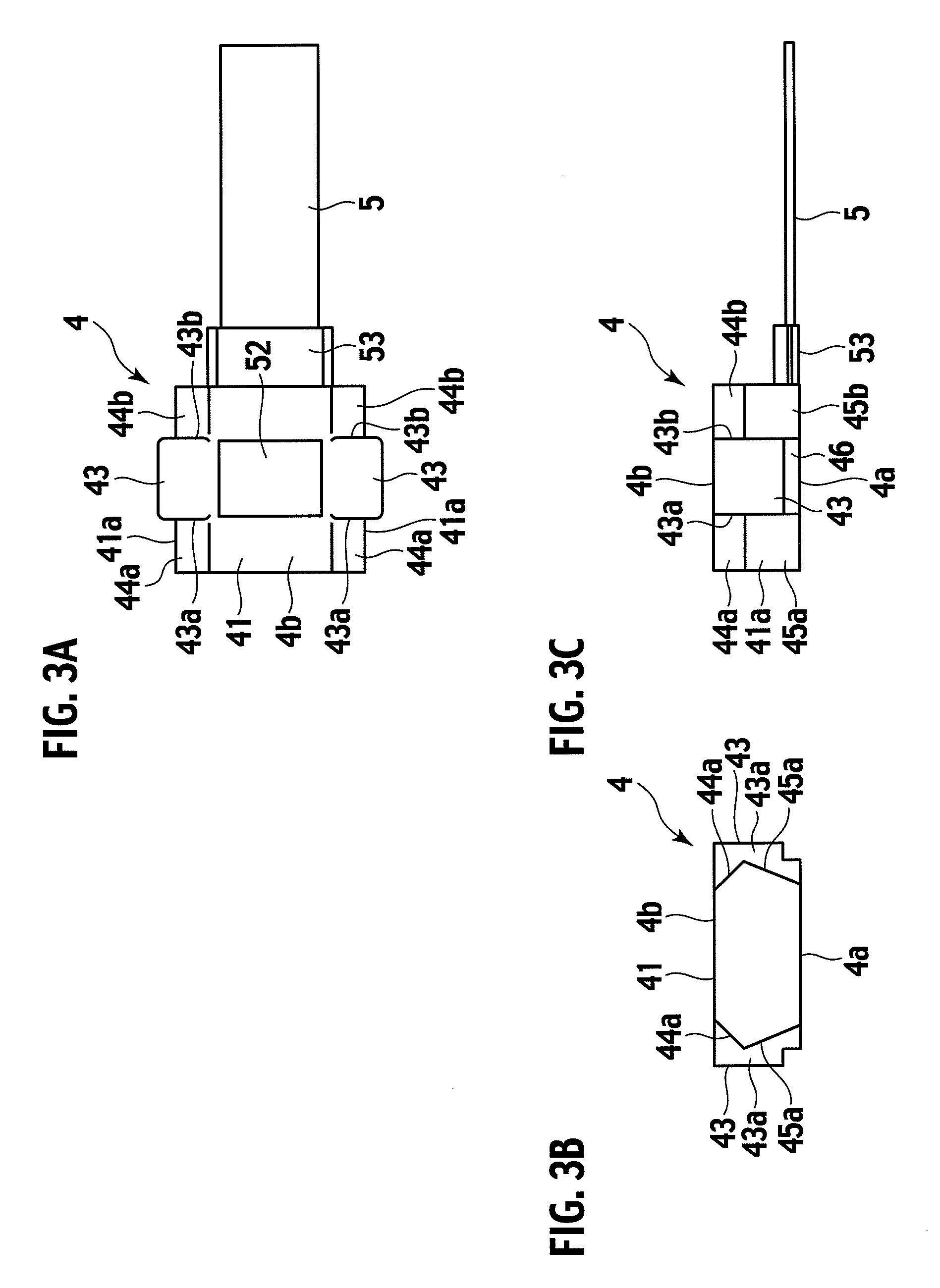
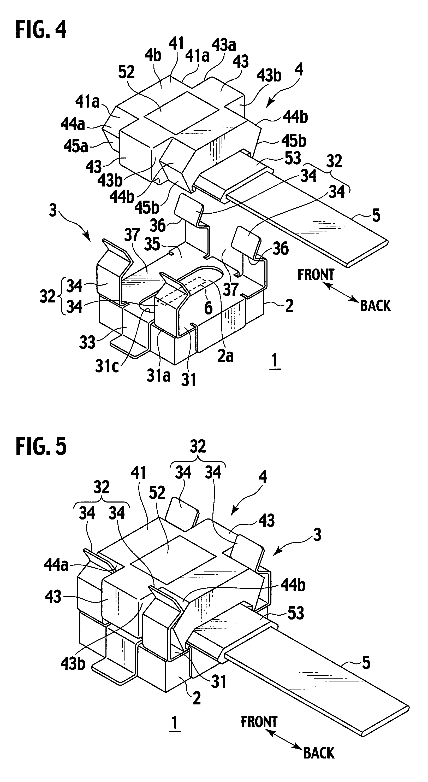
[0047]FIG. 1 is a cross-sectional view showing an optical path changing member 4 according to an embodiment of the present invention. FIG. 2 is an enlarged cross-sectional view showing a main part of the optical path changing member 4. FIGS. 3A to 3C are a plan view, a front view, and a side view showing the optical path changing member 4, respectively. FIGS. 4 and 5 are perspective views showing the optical path changing member 4 and a member holder 3, respectively.

[0048]As shown in these drawings, the optical path changing member 4 is assembled at ends 5a of optical fibers 5. The optical path changing member 4 is fixed to a photoelectric conversion module 2 on a circuit board 1 with the member holder 3.

[0049]The photoelectric conversion module 2 is equipped with an optical input / output terminal (photoelectric conversion elements) 6 which converts voltage / current into light or converts light into voltage / current. That is, the photoelectric conversion module 2 has the function to dr...


PUM


Abstract

An optical path changing member is assembled at ends of optical fibers and placed to face a substrate including an optical input / output terminal having optical axes inclined with respect to optical axes of the ends. The optical path changing member is made of a transparent material and includes a member body having a reflection surface for optically connecting the ends to the optical input / output terminal. The member body has optical fiber insertion holes and an end placement portion to which the insertion holes are open and in which the end faces of the optical fibers are placed. The reflection surface is formed so that light entering from the end faces of the optical fibers into the member body will be internally reflected toward the optical input / output terminal in the member body. The end placement portion is filled with an adhesive by which the ends are fixed to the member body.

Description

BACKGROUND OF THE INVENTION[0001]1. Field of the Invention[0002]The present invention relates to an optical path changing member to be assembled at ends of optical fibers, and particularly to an optical path changing member placed on a substrate provided with an optical input / output terminal so that the optical fibers are optically connected to the optical input / output terminal.[0003]2. Description of the Related Art[0004]In recent years, the following mechanism for optically connecting optical fibers to optical elements, such as light emitting elements (e.g. semiconductor lasers) and light receiving elements (e.g. photodiodes), has been widely used: the optical fibers are placed along a substrate having the optical elements mounted thereon; and an optical connector assembled at ends of the optical fibers is fixed to the substrate (see International Patent Publication WO / 2004 / 097480).[0005]The above-described optical connector has a structure for changing optical paths in order to o...

Claims


Application Information

Patent Timeline
Patent Type & Authority Applications(United States)
IPC IPC(8): G02B6/26
CPCG02B6/43G02B6/4214
Inventor OHTA, TATSUYAFUJIWARA, KUNIHIKONISHIMURA, AKITOSASAKI, KENJIHAYASHI, YUKIO
Owner THE FUJIKURA CABLE WORKS LTD
Why Eureka
Try Eureka