Optical transmission module and optical transmission system

a technology of optical transmission module and optical transmission system, which is applied in the direction of optical elements, instruments, semiconductor lasers, etc., can solve the problems of increasing the cost of optical transmission modules through which parallel optical transmission modules are connected, reaching their limits, and above-mentioned solutions are problematic in terms of costs

Inactive Publication Date: 2009-10-08
HITACHI METALS LTD
View PDF19 Cites 68 Cited by
  • Summary
  • Abstract
  • Description
  • Claims
  • Application Information

AI Technical Summary

Benefits of technology

[0034]According to the present invention, a bidirectional optical transmission module ...

Problems solved by technology

In metal wiring, however, transmission distances, transmission capacities, volumes, and weights have been increased to meet recent demands for significantly higher data transmission and larger capacities but their limits have been reached.
However, the above solutions are problematic in terms of costs because an apparatus with an increased number of optical transmission modules becomes large and expensive lasers and complex high-frequency circuits are required t...

Method used


Image

  • Optical transmission module and optical transmission system
  • Optical transmission module and optical transmission system
  • Optical transmission module and optical transmission system

Examples


first embodiment

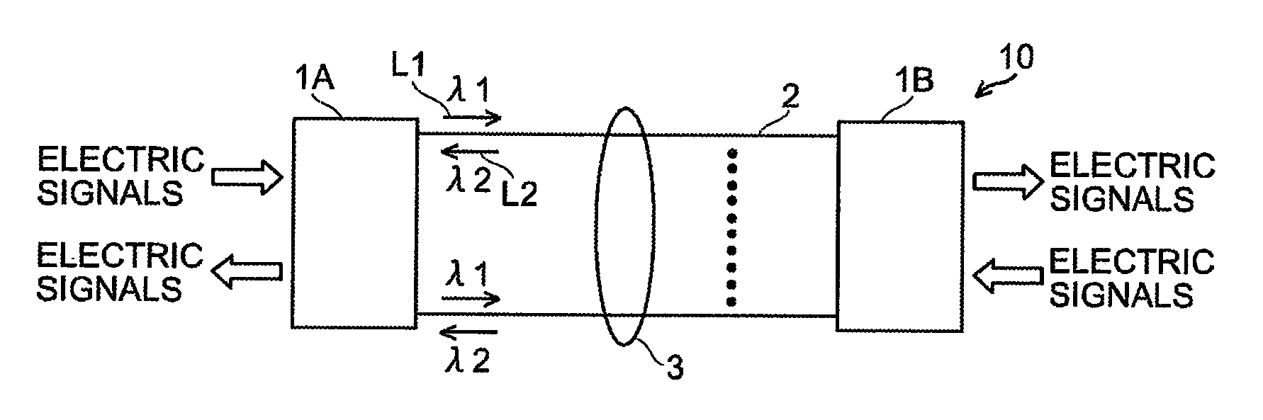
[0052]An optical transmission system using optical transmission modules in a preferable first embodiment of the present invention will be described with reference to FIG. 5.

[0053]In the optical transmission system (communication system) 10 shown in FIG. 5, optical transmission modules (multi-fiber bidirectional optical transmission modules or active connector modules) 1A and 1B (also collectively referred to below as optical transmission modules 1), according to the first embodiment, for converting electric signals to optical signals and vice versa are interconnected with a multi-fiber cable 3 formed by arranging a plurality of optical fibers 2 in parallel through which optical signals with different wavelengths are transmitted, so that transmission and reception can be carried out between the optical transmission modules 1A and 1B.

[0054]In this embodiment, a multi-mode fiber (MMF) is used as the optical fiber 2. A tape fiber formed by arranging 12 multi-mode fibers of this type for...

second embodiment

[0101]Next, a second embodiment will be described.

[0102]Although, in the first embodiment, the optical filter 17 that allows an optical signal to pass or reflects it depending on the wavelength that has been used as the optically functional member, a half mirror can also be used instead of the optical filter 17. Half mirrors lack a wavelength selecting function for performing demultiplexing or multiplexing according to the wavelength, but they allow the transmittance or reflectance of an optical signal with a predetermined wavelength to be set to an arbitrary value. That is, half mirrors have an almost fixed transmittance or reflectance, independent of the wavelength.

[0103]The half mirrors used in the optical transmission modules in the second embodiment are half mirrors HA and HB; the spectral characteristics of the half mirror HA is shown in FIGS. 13A1 and 13A2, a transmittance of 90% and a reflectance of 10% being obtained at a central wavelength of 880 nm; the spectral character...


PUM


Abstract

An optical transmission module includes one or more transmission optical devices for transmitting an optical signal L1, one or more reception optical devices for receiving another optical signal L2, and an optical member for converting optical paths for one or more optical signals L1 and one or more optical signals L2 having a different wavelength from the optical signal L1. The optical transmission module includes two or more inclined planes angled relative to the optical axis of the optical fiber, one of the two or more inclined planes has an optical filter for allowing these optical signals to partially or almost completely pass or partially reflect the optical signals L1 and L2; a reflecting plane for reflecting the optical signal L1 or L2 is formed on another one of the two or more inclined planes; a fiber lens is provided at a fiber-side end facing the optical fiber.

Description

TECHNICAL FIELD[0001]The present invention relates to an optical transmission module for converting electric signals to optical signals and vice versa, which is connected to another optical transmission module through optical fibers to send and receive the converted optical signals, and also relates to an optical transmission system that uses these optical transmission modules.BACKGROUND ART[0002]Network devices such as switches and routers and servers undergo distributed processing and cluster connection so that throughputs are increased.[0003]In metal wiring, however, transmission distances, transmission capacities, volumes, and weights have been increased to meet recent demands for significantly higher data transmission and larger capacities but their limits have been reached. Demands for optical transmission modules are rapidly increasing as a substitution for metal wiring.[0004]Conventional optical transmission modules mainly use single channels, in each of which two optical fi...

Claims


Application Information

Patent Timeline
IPC IPC(8): H04B10/12G02B5/04G02B5/26G02B5/28G02B6/42H01S5/022H01S5/183
CPCH04B10/40G02B6/4246
Inventor ISHIGAMI, YOSHIAKITAMURA, KENICHI
Owner HITACHI METALS LTD
Why Eureka
Try Eureka