Temperature adjustment mechanism and vehicle

a technology of temperature adjustment mechanism and temperature, which is applied in the direction of battery/fuel cell control arrangement, cell components, electrochemical generators, etc., can solve the problems of sometimes remarkable deformation of secondary cells, and achieve the effect of restrainting reducing excessive temperature rise of electric power supply devices

Inactive Publication Date: 2009-10-08
TOYOTA JIDOSHA KK
View PDF18 Cites 33 Cited by
  • Summary
  • Abstract
  • Description
  • Claims
  • Application Information

AI Technical Summary

Benefits of technology

[0013]In the foregoing aspect, the temperature adjustment mechanism may further be provided with control means for controlling the driving of the heat generator element based on a temperature of the electric power supply device, and the control means may cause the heat generator element to generate heat when the temperature of the electric power supply device is lower than a threshold. This restrains excessive temperature drop of the electric power supply device.
[0015]According to the invention, the member containing the PTC material is disposed between the electric power supply device and the heat transfer member, so that if the electric power supply device generates heat, the heat can be transferred to the heat transfer member via the member containing the PTC material. This restrains excessive temperature rise of the electric power supply device.
[0016]Furthermore, in the case where the heat transfer member is excessively heated, the member containing the PTC material can trip so that the transfer of heat from the heat transfer member to the electric power supply device less easily occurs. Thus, excessive temperature rise of the electric power supply device can be restrained.

Problems solved by technology

In particular, if the charging or discharging thereof is performed at high temperatures, the secondary cell can sometimes remarkably degrade.

Method used


Image

  • Temperature adjustment mechanism and vehicle
  • Temperature adjustment mechanism and vehicle
  • Temperature adjustment mechanism and vehicle

Examples


embodiment 1

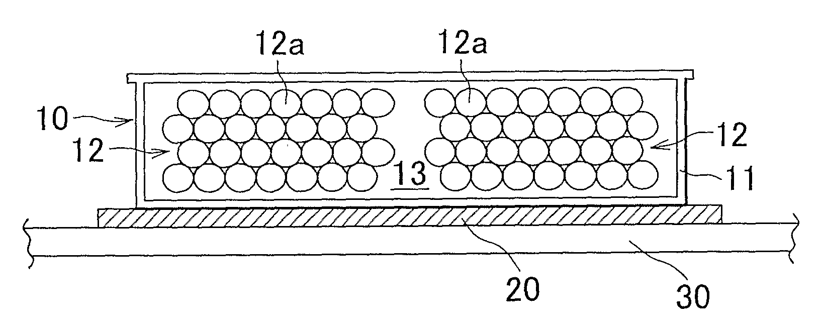
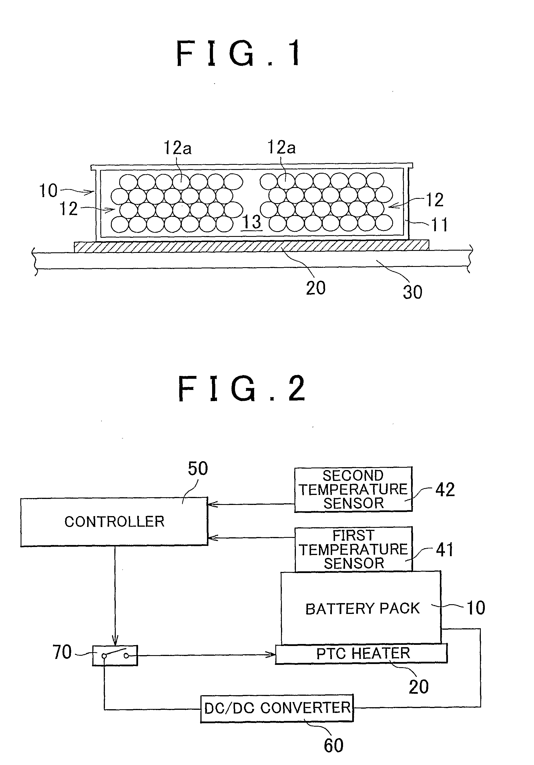
[0031]A temperature adjustment mechanism in accordance with Embodiment 1 of the invention will be described with reference to FIGS. 1 to 3.

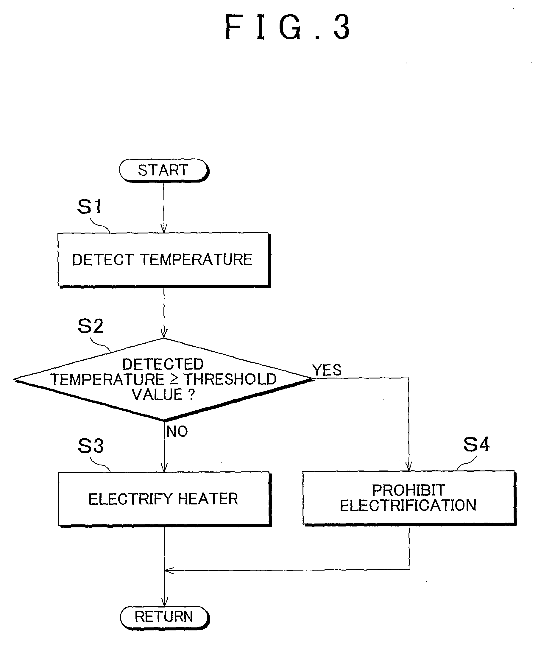
[0032]FIG. 1 is a sectional view schematically showing the temperature adjustment mechanism of a battery pack. FIG. 2 is a block diagram showing a construction that performs an operation control of the temperature adjustment mechanism, and FIG. 3 is a flowchart showing an operation control of the temperature adjustment mechanism. Incidentally, in FIGS. 1 to 3, the same members are represented by the same reference characters.

[0033]In FIG. 1, a battery pack (electric power supply device) 10 has a battery case 11, and a battery assembly (electric power supply body) 12 and a liquid 13 that are held within the battery case 11. The battery assembly 12 has a plurality of cylinder-shape electric cells 12a, and is clamped by a clamp member (not shown) from both end sides. Besides, the electric cells 12a are electrically connected in series by bus bars (n...

embodiment 2

[0076]A temperature adjustment mechanism in accordance with Embodiment 2 of the invention will be described with reference to FIG. 4. FIG. 4 is a schematic diagram showing a construction of a temperature adjustment mechanism of the embodiment. Incidentally, the members that have the same functions as the members described above in conjunction with Embodiment 1 are represented by the same reference characters.

[0077]In this embodiment, the battery pack 10 has a battery case 11, and a battery assembly 12 and a liquid 13 that are held in the battery case 11, as in Embodiment 1.

[0078]Furthermore, a stirring member 14 for stirring the liquid 13 within the battery case 11 is disposed within the battery case 11. The stirring member 14, as shown in FIG. 5, has a shaft portion 14a that extends along a wall surface of the battery case 11, and stirring blades 14b that are formed on a surface of the shaft portion 14a.

[0079]The stirring member 14 is not limited to the construction as shown in FI...


PUM

PropertyMeasurementUnit
Curie temperatureaaaaaaaaaa
voltageaaaaaaaaaa
temperatureaaaaaaaaaa

Abstract

A temperature adjustment mechanism has an electric power supply device, and a member that is provided between and in contact with the electric power supply device and a heat transfer member and that contains a PTC material.

Description

BACKGROUND OF THE INVENTION[0001]1. Field of the Invention[0002]The invention relates to a temperature adjustment mechanism capable of restraining excessive temperature rise or excessive temperature drop of an electric power supply body.[0003]2. Description of the Related Art[0004]The vehicles that run by the drive force from an electric motor include hybrid motor vehicles, fuel cell vehicles, and electric motor vehicles. In these vehicles, a secondary cell or a capacitor (condenser) that stores electric power to be supplied to the electric motor is mounted. The performance and the service life of the secondary cell are greatly dependent on the ambient temperature. In particular, if the charging or discharging thereof is performed at high temperatures, the secondary cell can sometimes remarkably degrade.[0005]Therefore, in order to restrain the degradation of the secondary cell, constructions for cooling the secondary cell have been proposed.SUMMARY OF THE INVENTION[0006]The inventi...

Claims


Application Information

Patent Timeline
Patent Type & Authority Applications(United States)
IPC IPC(8): H01M10/50B60K11/02H01M10/60H01M10/615H01M10/625H01M10/633H01M10/637H01M10/643H01M10/647H01M10/6561H01M10/6567H01M10/6569H01M10/6571H01M50/202
CPCB60L11/1874H01M2/105H01M2/1077H01M10/5006Y02T10/705H01M10/503H01M10/5075H01M10/5083Y02T10/7005H01M10/5016H01M10/625H01M10/615H01M10/6571H01M10/6567H01M10/643B60L58/26Y02T10/70Y02E60/10H01M50/213H01M50/202
Inventor TAKAGI, MASARU
Owner TOYOTA JIDOSHA KK
Why Eureka
Try Eureka