Valve manifold assembly

a manifold and valve technology, applied in the field of valves, can solve the problems of affecting the operation of valves, and presenting certain drawbacks that are not desirable in particular semiconductor applications, and reducing the service life of valves, so as to minimize the exposure of the operative portions

Active Publication Date: 2009-10-15
ENTEGRIS INC
View PDF15 Cites 21 Cited by
  • Summary
  • Abstract
  • Description
  • Claims
  • Application Information

AI Technical Summary

Benefits of technology

[0007]An improved valve manifold combination system and associated methods of eliminating dead space and obstructions in the a main fluid flow duct of the manifold and minimizing exposure of the operative portions of the valve to the primary fluid duct are described herein. The invention in an embodiment includes a manifold with a main fluid flow duct and at least one valve mounted on the manifold in a valve region. The at least one valve has a valve stem wit

Problems solved by technology

Although prior valve-manifold combinations effectively provide for the transport and mixing of multiple fluids, they still present certain drawbacks that are not desirable in particular semiconductor applications.
For example, some prior manifolds produce quiescent or dead spots in the primary fluid flow duct which could cause fluids to become stagnant and degrade or could trap solids resulting from fluid conta

Method used


Image

  • Valve manifold assembly
  • Valve manifold assembly
  • Valve manifold assembly

Examples


Embodiment Construction

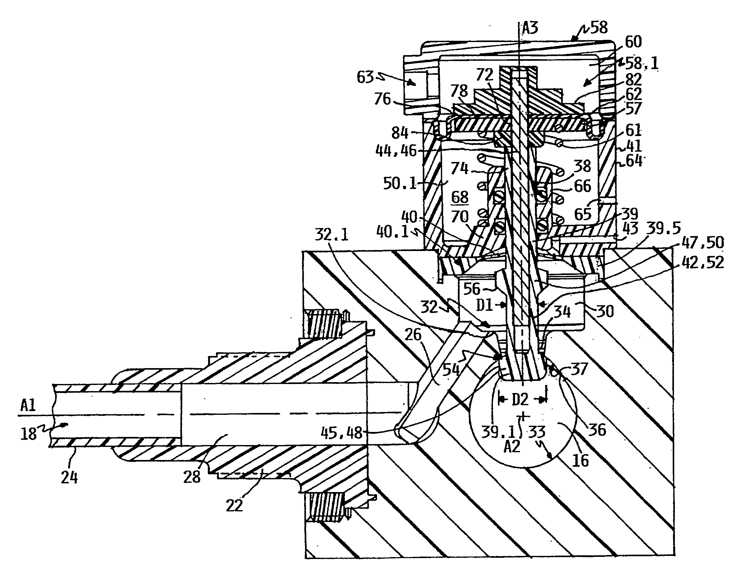
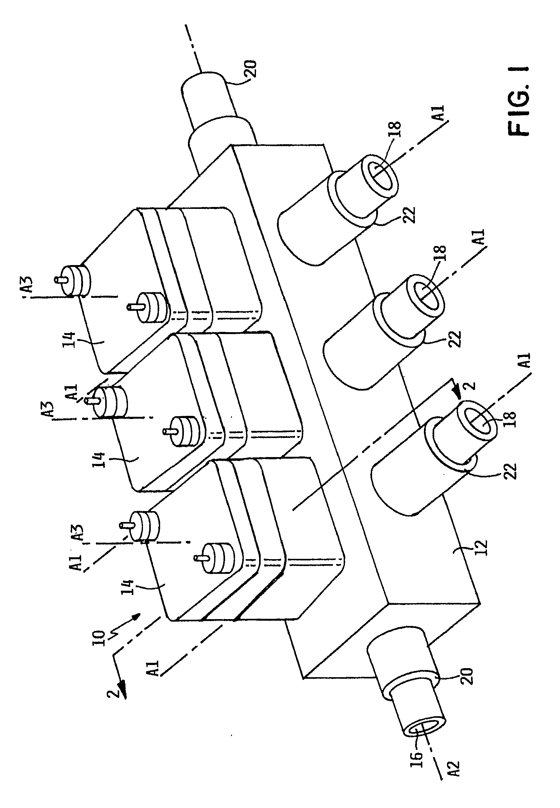
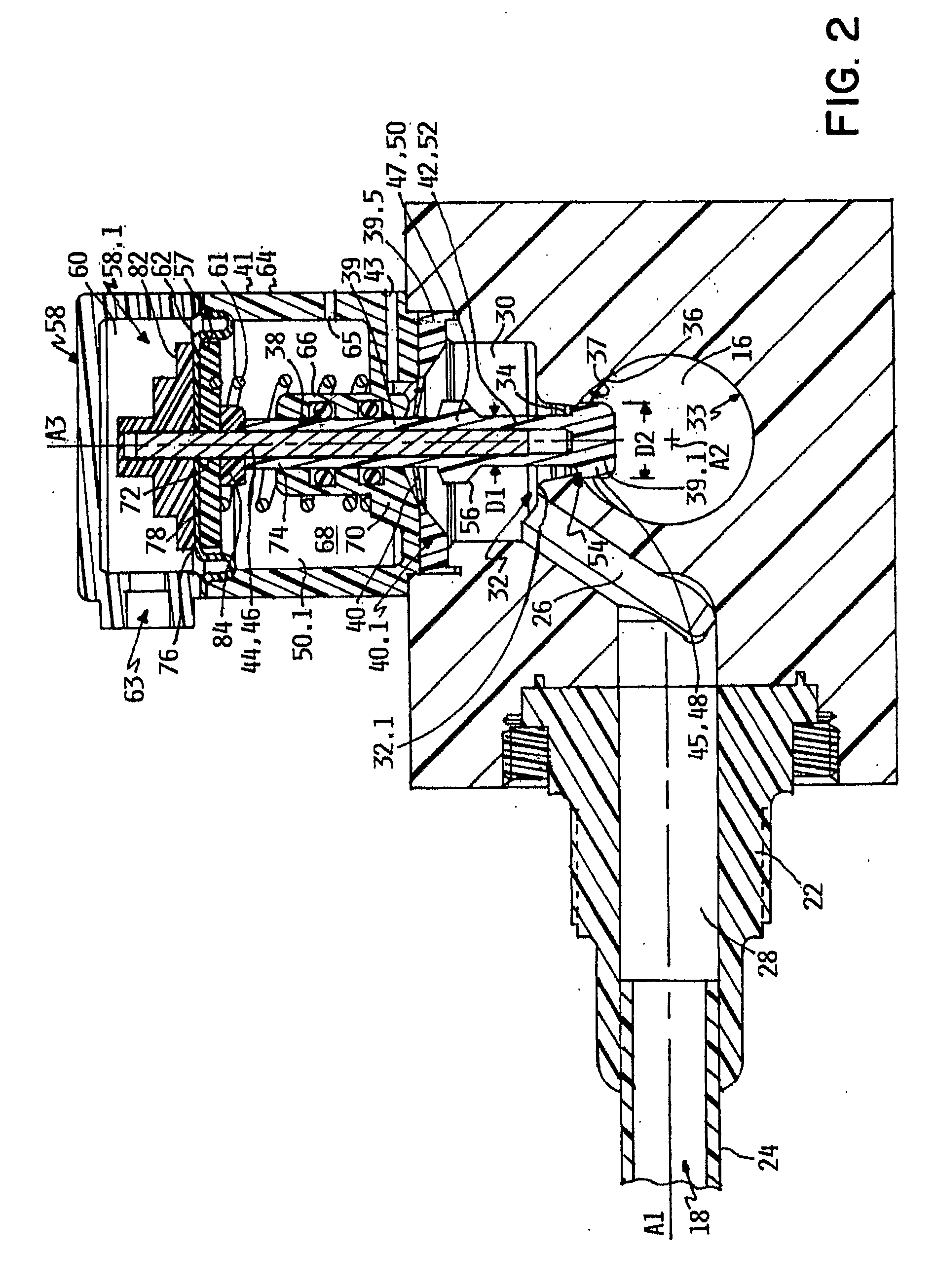
[0025]A mixing valve manifold assembly 10 is depicted in FIG. 1 and generally includes a manifold body portion 12 and a plurality of valve assemblies 14. Manifold body portion 12 defines a primary flow passage 16 oriented along longitudinal axis A2 and a plurality of secondary flow passages 18 oriented along axes A1 extending generally transverse to primary flow passage 16. Manifold body portion 12 further includes primary flow connectors 20 at each end of primary flow passage 16 for coupling tubing (not depicted), and secondary flow connectors 22 are provided for connecting tubing 24 to secondary flow passages 18. Connectors 20, 22, may be a conventional Flaretek® fitting, available from Entegris, Inc, the owner of the instant invention. Connectors 20, 22, manifold body portion 12, and any other wetted components may preferably be formed of fluoropolymers, such as PFA (perfluoroalkoxy), PTFE (polytetrafluoroethylene), or modified PTFE (for example NXT70 by Dupont).

[0026]Referring n...


PUM


Abstract

A valve manifold assembly including a manifold body defining a primary flow passage and a secondary flow passage fluidly coupled therewith through an aperture in the wall of the primary flow passage. A valve including a head portion and a stem extending therefrom is disposed through the aperture. The head portion has a valve sealing surface adjacent and extending around the stem, and a valve seat having a seat sealing surface facing into the primary flow passage extends around the aperture. The valve is selectively shiftable between a closed position wherein the valve sealing surface is sealingly engaged with the seat sealing surface to block fluid flow between the secondary flow passage and the primary flow passage, and an open position wherein the valve sealing surface is spaced apart from the seat sealing surface to enable fluid flow between the secondary flow passage and the primary flow passage.

Description

RELATED APPLICATIONS[0001]This application claims the benefit of U.S. Provisional Patent Application No. 60 / 831,070 entitled VALVE MANIFOLD COMBINATION, filed Jul. 14, 2006, and hereby fully incorporated herein by reference.FIELD OF THE INVENTION[0002]The present invention relates to valves, and more particularly, to a valve manifold assembly for mixing secondary fluids into a primary fluid.BACKGROUND OF THE INVENTION[0003]Various types of valves are used in the semiconductor industry to control fluid transport and to mix fluids, including highly pure and highly caustic fluids. Although prior valve-manifold combinations effectively provide for the transport and mixing of multiple fluids, they still present certain drawbacks that are not desirable in particular semiconductor applications.[0004]For example, some prior manifolds produce quiescent or dead spots in the primary fluid flow duct which could cause fluids to become stagnant and degrade or could trap solids resulting from flui...

Claims


Application Information

Patent Timeline
IPC IPC(8): F16K11/22
CPCB01F5/0077B01F15/0429F16K31/1264F16K11/20F16K27/003B01F2215/0096Y10T137/87249Y10T137/8766Y10T137/87684B01F25/105B01F35/833B01F2101/58F16K1/06H01L21/02
Inventor LEYS, JOHN A.
Owner ENTEGRIS INC
Why Eureka
Try Eureka