Active muffler

a technology of active mufflers and mufflers, which is applied in the direction of mechanical equipment, machines/engines, instruments, etc., to achieve the effect of reducing heat transfer and preventing heat bridges

Active Publication Date: 2009-10-15
PUREM GMBH
View PDF25 Cites 26 Cited by
  • Summary
  • Abstract
  • Description
  • Claims
  • Application Information

AI Technical Summary

Benefits of technology

[0006]The present invention relates to the problem of providing an improved embodiment for an active muffler of the type defined in the introduction and for an exhaust gas system equipped with it such that it is characterized in particular by the fact that the risk of damage to the muffler due to overheating and / or due to condensation is reduced, while also implementing a comparatively large rear volume.
[0008]One embodiment of the invention is based on the general idea of constructing a housing to hold the loudspeaker in a shell construction with two pot-shaped shells, a funnel-shaped sound conducting body being accommodated in the interior of the housing. This sound conducting body passes out of the housing through the bottom shell with a connection on the one hand, while on the other hand serving to attach the loudspeaker to a flange section. A bypass is provided, bypassing the flange section and allowing a communicating connection between an interior space of the top shell and an interior space of the bottom shell. The volume of the interior of the bottom shell outside of the sound conducting body and the volume of the interior of the top shell apart from the loudspeaker together thus form the rear volume of the loudspeaker. A relatively large rear volume for the loudspeaker can be implemented in this way with a comparatively compact design. The hot exhaust gas may pass through the sound conducting body more or less from the bottom to the diaphragm of the loudspeaker, thereby implementing a certain minimum distance across the sound conducting body and preventing a direct effect of hot exhaust gases on the diaphragm and / or loudspeaker. At the same time, this installation situation ensures that condensate can flow out of the loudspeaker and / or its diaphragm comparatively easily and / or can be removed namely through the sound conducting body. The arrangement of the loudspeaker together with the sound conducting body in a separate housing also makes it possible to position the active muffler especially easily on an exhaust gas system, so that overheating of the loudspeaker can be prevented. For example, it is especially easy to maintain minimum distances from hot lines carrying exhaust gas. Furthermore, the housing may be mounted on the vehicle especially easily, so that it is exposed to the slip stream during operation of the vehicle. Furthermore, the muffler forms a unit that can be prefabricated and can be used more or less universally, regardless of the specific installation situation.
[0009]An embodiment in which the sound conducting body in the installed state of the muffler forms a drain in its interior leading from the flange section to the connection is especially advantageous. In this way, condensate that may collect on the diaphragm during operation of the muffler, e.g., on the exhaust end, can be removed from the muffler especially easily.
[0010]Said drain can be embodied especially without steps and / or undercuts, thus preventing water from collecting in the muffler and reducing the risk of icing associated with this.
[0012]In another advantageous embodiment, it is possible to provide for the flange section to be equipped with several radial protrusions on the outside radially spaced a distance apart in the circumferential direction, supported on the outside radially on an inner side of the bottom shell. This support may be designed in particular with a tight fit and / or a friction fit, such that no additional separate fastening elements, e.g., screws, are necessary for fastening the sound conducting body. This makes it possible to prevent heat bridges between the housing and the sound conducting body, which reduces the transfer of heat to the loudspeaker.

Problems solved by technology

Furthermore, the housing may be mounted on the vehicle especially easily, so that it is exposed to the slip stream during operation of the vehicle.

Method used


Image

  • Active muffler
  • Active muffler
  • Active muffler

Examples


Embodiment Construction

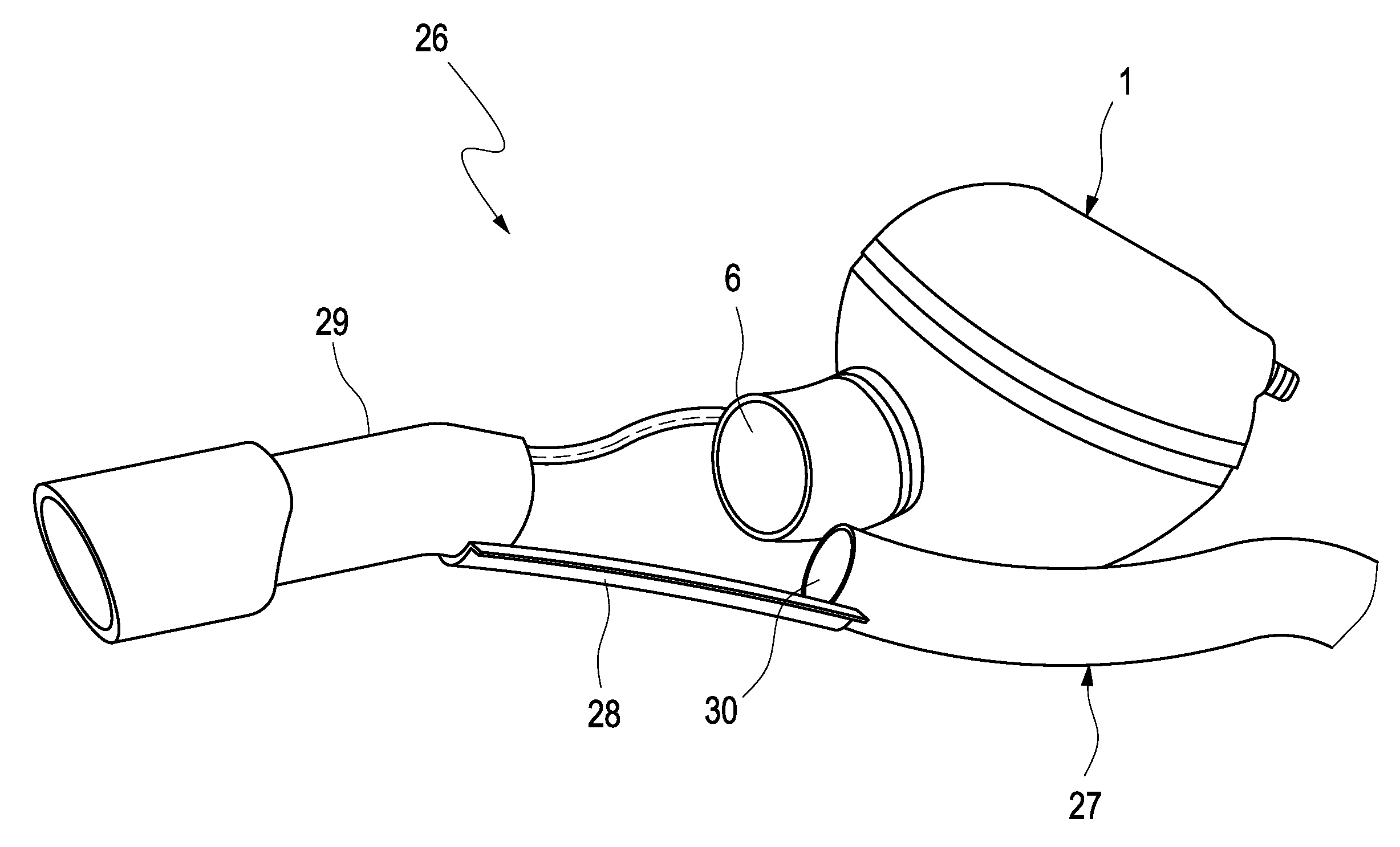
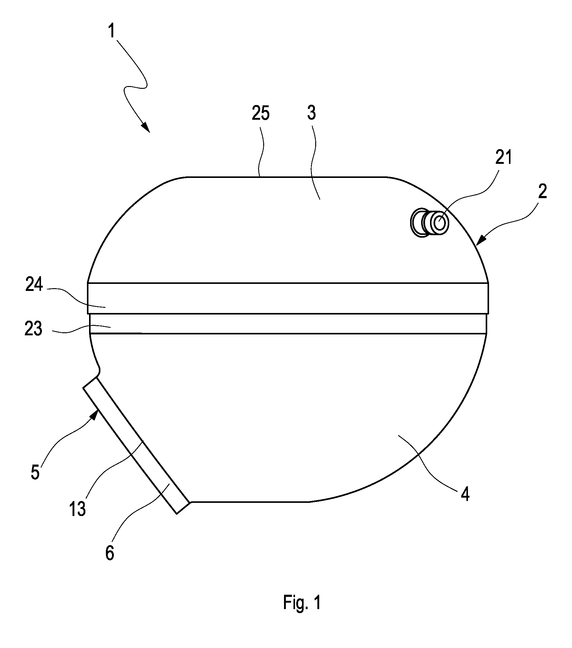
[0023]According to FIGS. 1 to 4, an active muffler 7 comprises a housing 2, which is designed with multiple shells, preferably two shells, and has at least one top shell 3 and one bottom shell 4 accordingly. The top shell 3 and bottom shell 4 are each designed in the form with a pot shape. On the whole, this yields an essentially spherical shape of the housing 2.

[0024]The muffler 1 contains in its housing 2 a sound conducting body 5 which is designed with a funnel shape and has a connection 6 and a flange section 7. The connection 6 serves to connect the muffler 1 to a space or a line in which airborne sound propagates; this sound should be actively suppressed with the help of the muffler 1.

[0025]For active sound suppression, the muffler 1 has a loudspeaker 8, which has a conventional design. Accordingly, the loudspeaker 8 has an electromechanical converter 9, which is attached to a cage and may excite a diaphragm 11 to vibration, said diaphragm being stretched over the cage 10. Fur...


PUM


Abstract

The present invention to an active muffler for an exhaust gas system of an internal combustion engine, in particular in a motor vehicle, includes a multi-shell housing having a pot-shaped top shell and a pot-shaped bottom shell, a funnel-shaped sound conducting body, which is inserted into the bottom shell and has a connection passing through the bottom shell and out of the housing, a loudspeaker, which is situated in the top shell and is attached to a flange section of the sound conducting body at a distance from the connection, such that a free inside cross section of the sound conducting body surrounded by the flange section is closed with an airtight seal, and a bypass through which an interior space of the top shell is connected to an interior space of the bottom shell so they communicate.

Description

CROSS-REFERENCE TO RELATED PATENT APPLICATIONS[0001]This patent application claims the benefit of co-pending German Patent Application No. DE 102008018085.8, filed on Apr. 9, 2008, the entire teachings and disclosure of which are incorporated herein by reference thereto.FIELD OF THE INVENTION[0002]The present invention relates to an active muffler for an exhaust gas system of an internal combustion engine, in particular in a motor vehicle. The invention also relates to an exhaust gas system equipped with such an active muffler for an internal combustion engine, in particular in a motor vehicle.BACKGROUND OF THE INVENTION[0003]Active mufflers work with anti-noise, which is actively generated by at least one loudspeaker and can be used by phase cancellation to attenuate, i.e., suppress certain frequencies, e.g., to reduce noise emission into the environment by an exhaust gas system of an internal combustion engine.[0004]Active mufflers are known, for example, from U.S. Pat. No. 5,600,...

Claims


Application Information

Patent Timeline
Patent Type & Authority Applications(United States)
IPC IPC(8): F01N1/06F01N13/18
CPCF16L55/0333F01N1/065
Inventor KRUGER, JANCASTOR, FRANKMULLER, MANFREDWIRTH, GEORG
Owner PUREM GMBH
Why Eureka
Try Eureka