
Motor module

a technology of motor modules and motor casings, applied in the direction of capacitors, electric devices, battery/cell propulsion, etc., can solve the problems of increasing the length of the motor module, affecting the mountability, and the inability to perform parallel assembly operations of the respective electric motors, so as to facilitate the operation of completing the terminal block and avoid the increase in the rotation axis. , the effect of improving the workability or processing capacity of the casing

Inactive Publication Date: 2009-10-15
TOYOTA JIDOSHA KK +1
View PDF5 Cites 27 Cited by
  • Summary
  • Abstract
  • Description
  • Claims
  • Application Information

AI Technical Summary

Benefits of technology

[0010]The invention has been made for overcoming the above problems, and an object of the invention is to provide a motor module that is provided with a plurality of electric motors neighboring to each other in a rotation axis direction, and particularly to provide a structure of connection mechanisms between power cables and electric motors that can prevent increase in size in the rotation axis direction and can improve assembly workability.

Problems solved by technology

However, this structure increases a length of the motor module in the rotor rotation axis direction, and may impair mountability.
Since the two electric motors are accommodated in the same casing, assembly operations for the respective electric motors cannot be performed in parallel without difficulty.
This may cause complication of the assembly operations as well as increase in time required for them, and thus may deteriorate productivity.
Further, if the connection structure for the power cable and the electric motor has an opening in the housing or casing as disclosed in the Patent Document 4, this may cause disadvantages such as increase in number of parts for a sealing structure and oil leakage due to insufficient sealing property.

Method used


Image

  • Motor module
  • Motor module
  • Motor module

Examples


Embodiment Construction

[0055]Embodiments of the invention will now be described with reference to the drawings. In the following description, the same or corresponding portions bear the same reference numbers, and description thereof is not repeated.

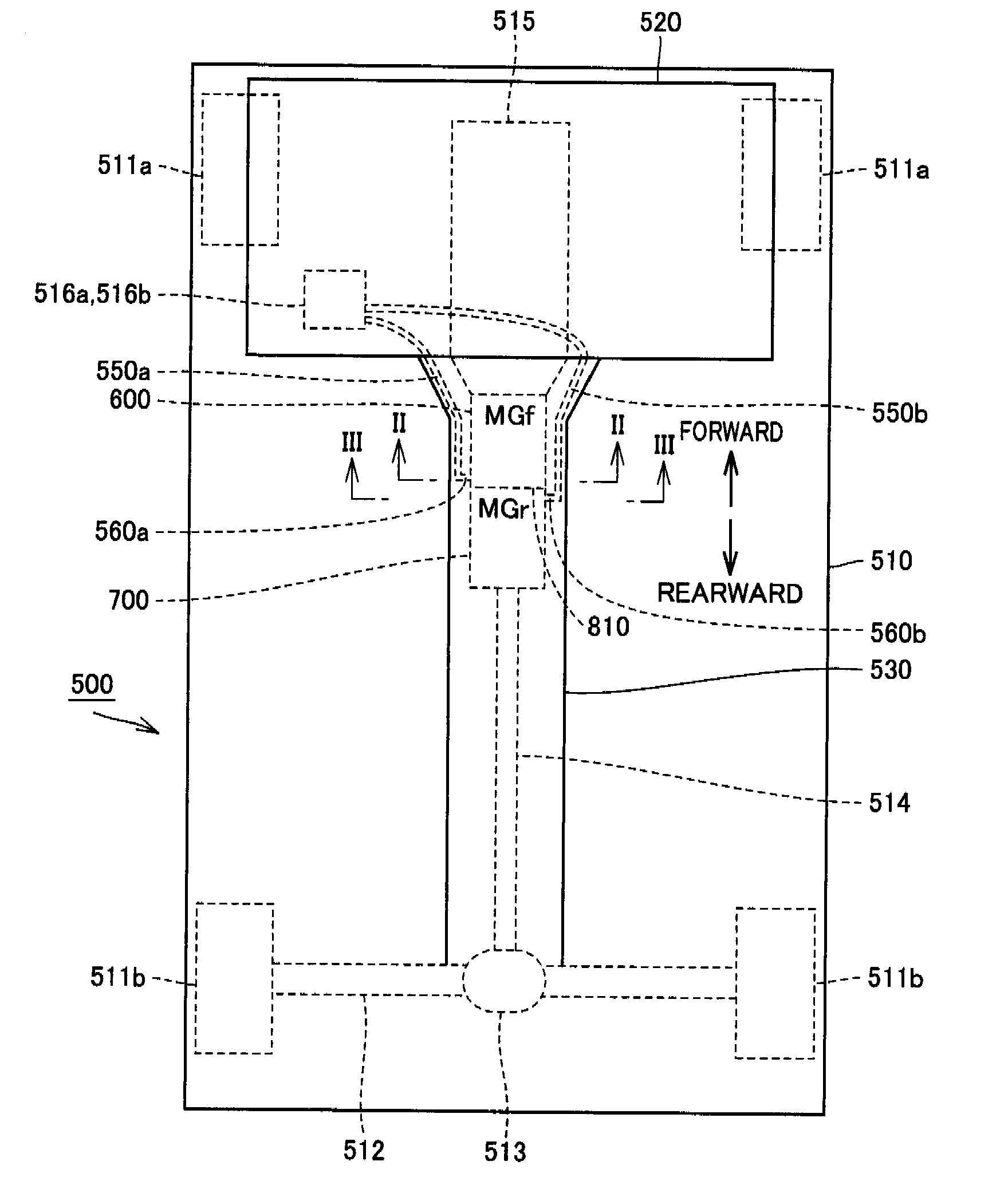
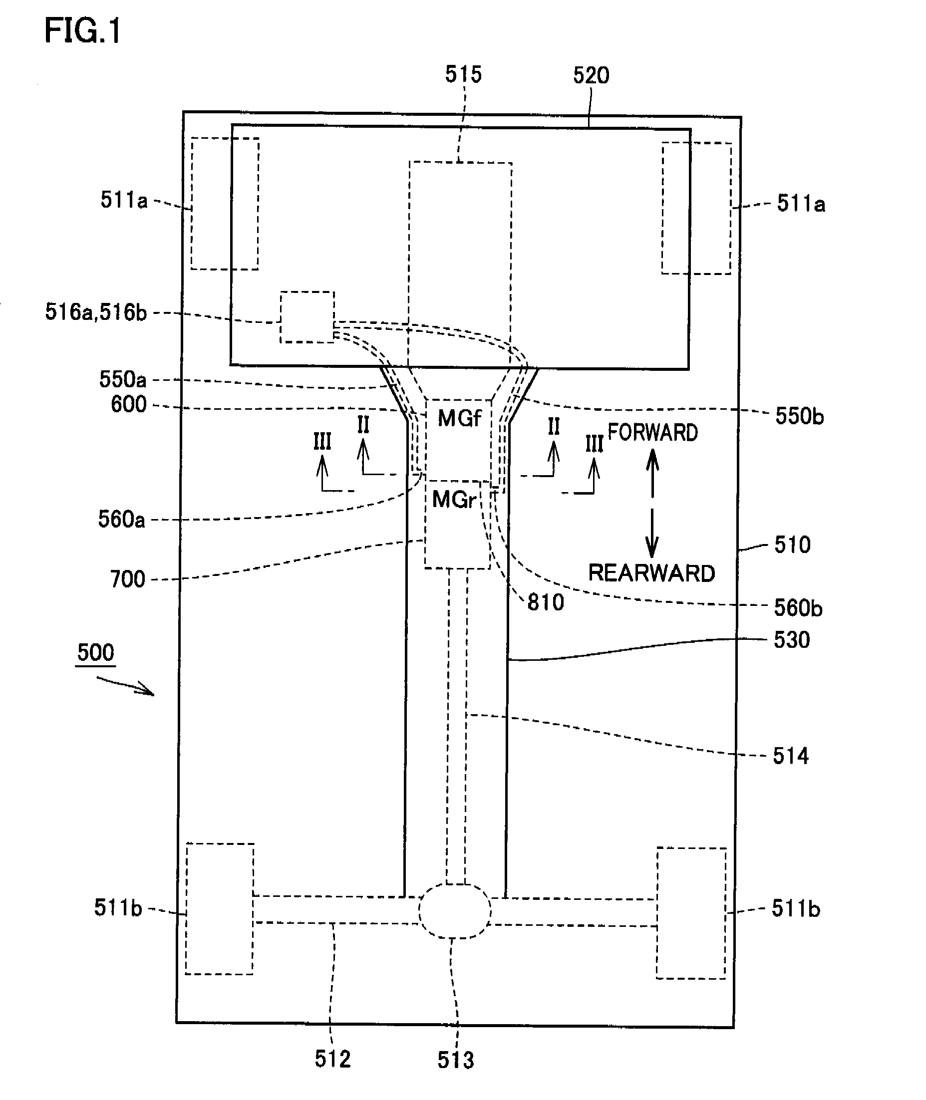
[0056]FIG. 1 is a schematic block diagram showing a structure of a hybrid vehicle that is an example of a structure equipped with a motor module according to the invention. FIG. 1 shows an example in which the motor module is mounted on the hybrid vehicle of an FR (Front-engine Rear-drive) type having two electric motors (motor generators) neighbor to each other in an axial direction (a longitudinal direction of a vehicle).

[0057]Referring to FIG. 1, a hybrid vehicle 500 of the FR type includes a chassis 510. An engine compartment 520 in which an engine 515 is arranged and a tunnel 530 communicated with engine compartment 520 are formed by chassis 510. Front and rear wheels 511a and 511b are arranged at four corners of chassis 510, respectively.

[0058]Engine com...


PUM


Abstract

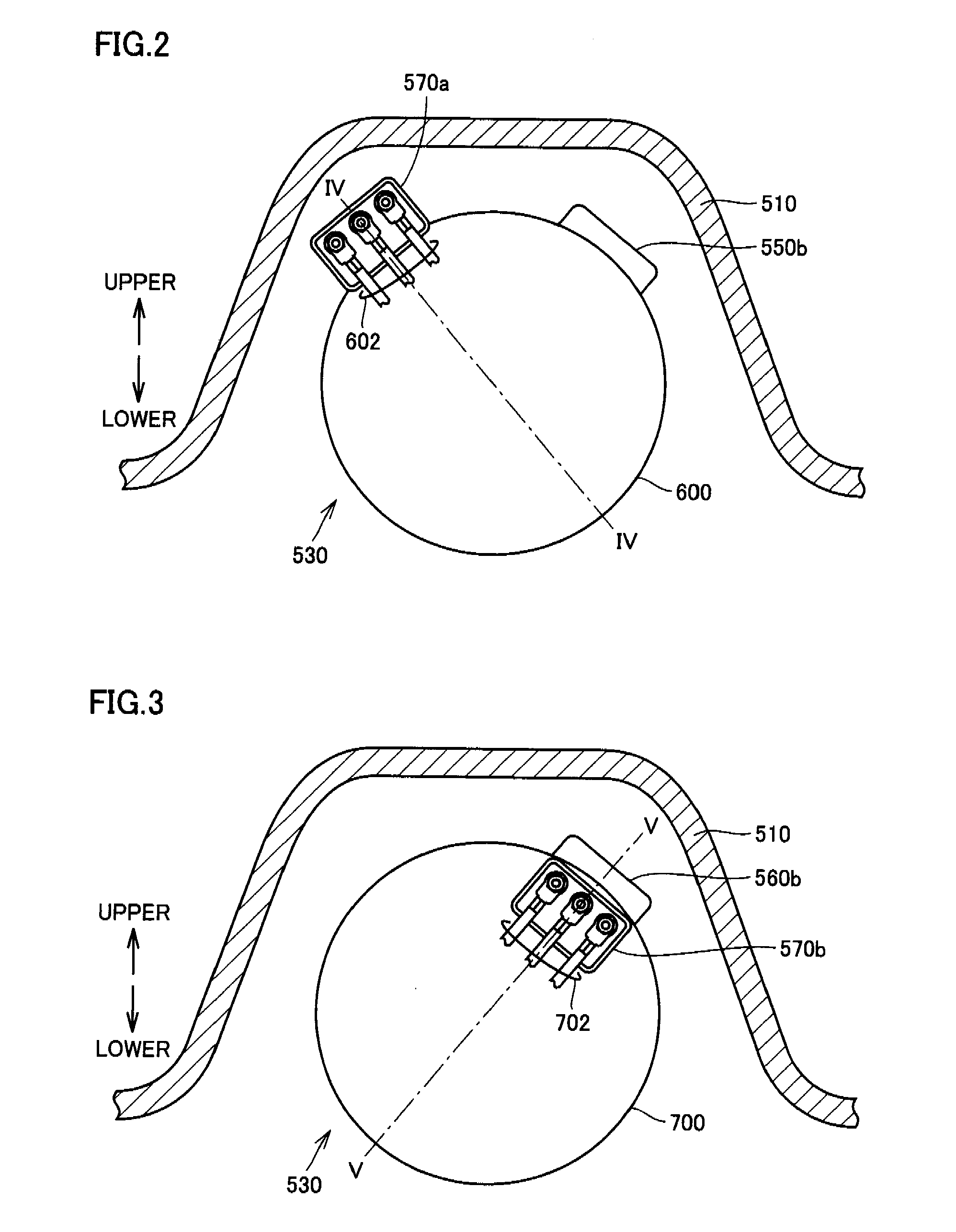
First and second connection mechanisms electrically connect power cables extending in the same direction to first and second electric motor neighboring to each other in the extending direction of the power cables, respectively. The first connection mechanism of the first electric motor is arranged in a radially outer portion, and the second connection mechanism of the second electric motor is arranged in a space between the electric motors. Since both the connection mechanisms are located on the opposite sides of a joint surface between the first and second casings accommodating the first and second motors, respectively, the first and second connection mechanisms can be components on the first and second casing sides, respectively. This structure can prevent increase in size in a rotation axis direction, and can improve assembly workability for the motors.

Description

TECHNICAL FIELD[0001]The invention relates to a motor module, and particularly to a motor module having a plurality of electric motors that neighbor to each other in a direction of a rotor rotation axis.BACKGROUND ART[0002]Vehicles such as an electric vehicle and a hybrid vehicle that are equipped with electric motors (including motors and motor generators in this invention) as drive power sources have been developed. These vehicles generally have a structure in which an electric motor is accommodated in a casing for protecting the electric motor from an external environment or for housing the electric motor integrally with a transmission and thereby sealedly keeping its Automatic Transmission Fluid (ATF). Since an electric power supply of the electric motor is arranged outside the casing, a mechanism is required for electrically connecting this power supply to the electric motor in the casing.[0003]For example, Japanese Patent Laying-Open No. 2004-120961 (Patent Document 1) has dis...

Claims


Application Information

Patent Timeline
IPC IPC(8): H02K11/00
CPCH02K16/00H02K5/225B60L2210/40B60L2220/50B60L50/16B60L50/40B60L50/61Y02T10/62Y02T10/64Y02T10/70Y02T10/7072Y02T10/72
Inventor MIURA, TETSUYAIHARA, HIROTATSUTAKEUCHI, TAKAMASASENOO, MASAMITSUTANAKA, AKIHIROKOSHIDA, TAKAFUMIATARASHI, TOMOO
Owner TOYOTA JIDOSHA KK
Learn More