Form c relay and package using same

a technology of relays and relays, applied in the field of switching devices, can solve the problems of increasing the complexity of the device with a higher cost, long, unprotected and vulnerable connection, and significant parasitic capacitance c to ground, and achieve the effect of minimizing the discontinuity of impedan

Inactive Publication Date: 2009-10-15
COTO TECH
View PDF35 Cites 4 Cited by
  • Summary
  • Abstract
  • Description
  • Claims
  • Application Information

AI Technical Summary

Benefits of technology

[0045]Another object of the present invention is to minimize impedance discontinuities by altering the configuration of the shielding of the device.

Problems solved by technology

It can be understood, such multi-pole switching adds complexity to the device with a higher cost.
However, as is well known in the art, this results in a long, unprotected and vulnerable connection between the terminals of the reed switches and the circuit board which is commonly termed a “stub connection.” As a result of this long, unprotected stub connection, significant parasitic capacitance C to ground will be present.
Unfortunately, prior art reed switch devices configurations include a stub connection on the circuit board that makes the device essentially incapable of testing high-speed devices.
This transition of the signal leads from plastic dielectric to air creates an undesirable discontinuity of the protective co-axial environment found within the body of the switch itself.
Such discontinuity creates inaccuracy and uncertainty in the impedance of the reed switch device.
This method of discontinuity compensation is not preferred because it complicates and slows the design process and can degrade the integrity of the circuit.
This is particularly problematic with very high frequency circuit environments, such as ones that operate in the 18 GHz and higher.
However, such tuning compensation schemes only work over a relatively narrow range of frequency.
The prior art uses a structure of carefully designed vias, which are expensive and difficult to manufacture, to control the impedance from the relay to the board transition.

Method used


Image

  • Form c relay and package using same
  • Form c relay and package using same
  • Form c relay and package using same

Examples


Embodiment Construction

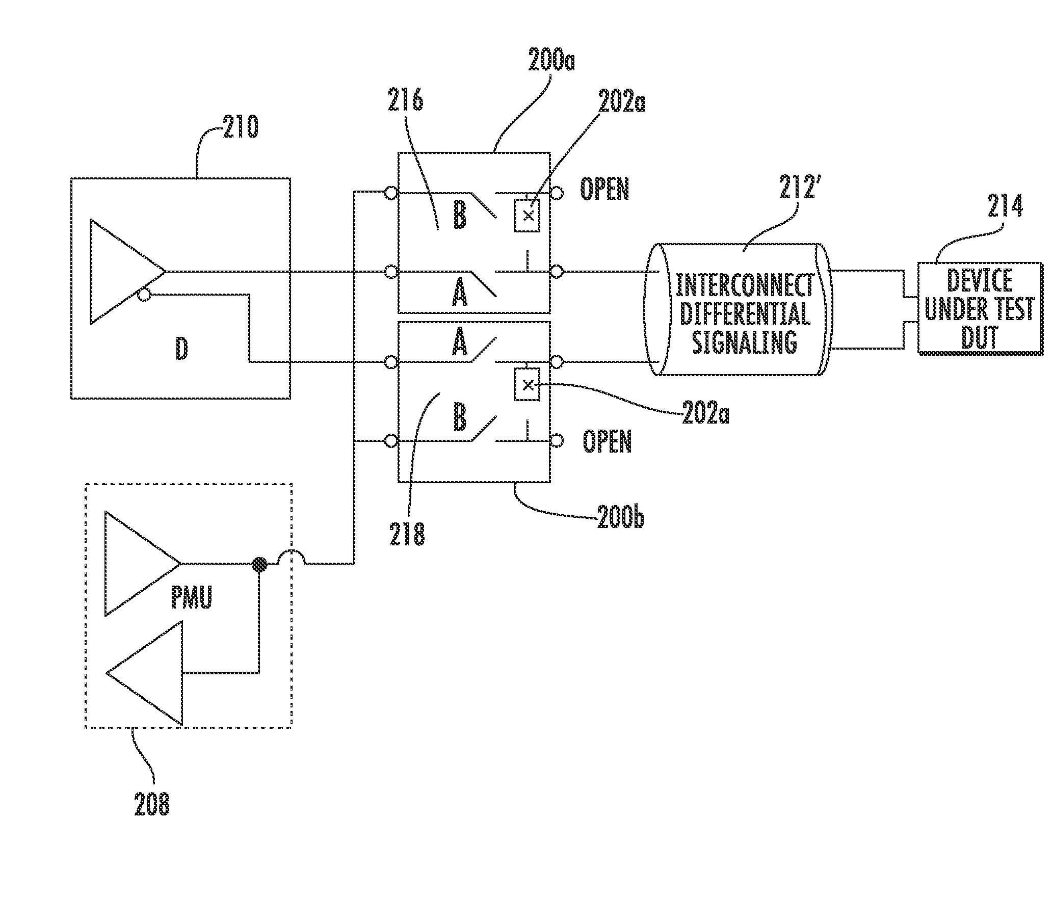
[0073]The improved Form C relay 200 of the present invention is shown in detail in connection with FIGS. 9-26 below. The relay of the present invention may be easily used for circuits, such as circuit 300 in FIG. 7 so that this circuit may easily operate at frequencies in the 18 GHz range and above to accommodate the testing of high-speed devices. The relay 200 of the present invention can enable such circuits to operate in the 18 GHz range and higher because RF performance is greatly improved by use of low pass filters, generally referred to as 202, while the high-frequency path is protected using the simulated co-axial signal protecting environment. Also, a DC signal to about 18 GHz on either channel in a dual channel environment, with less than 3 dB signal power loss, can be achieved in a circuit that employs the relay of the present invention. The relay 200 of the present invention is the first to use two filter elements, such as 202a and 202b as in FIG. 9, to mutually isolate t...


PUM


Abstract

The improved reed relay package provided a “pseudo” Form C relay that includes two Form A relays with at least one bridge filter element electrically interconnecting the signal outputs thereof to reduce stub capacitance and improve RF performance. As a result, the reed relay package can operate at very high frequencies, such as 18 GHz and higher. Also, vias can be provided through the support substrate to simulate a co-planar waveguide and RF shields profiled with cut-outs to better simulate a 50 ohm impedance environment throughout the path of the signal line.

Description

CROSS REFERENCE TO RELATED APPLICATION[0001]This application is related to and claims priority from earlier filed provisional patent application Ser. No. 61 / 045,174, filed Apr. 15, 2008, the entire contents thereof is incorporated herein by reference.BACKGROUND OF THE INVENTION[0002]The present invention relates generally to switching devices. More specifically, the present invention relates to improved packaging and circuit integration for electromagnetic devices, such as reed switches and electromagnetic devices such as reed relays.[0003]Electromagnetic relays have been known in the electronics industry for many years. Such electromagnetic relays include the reed relay which incorporates a reed switch. A reed switch is typically a magnetically activated device that typically includes two flat contact tongues which are merged in a hermetically sealed glass tube filled with a protective inert gas or vacuum. The switch is operated by an externally generated magnetic field, either fro...

Claims


Application Information

Patent Timeline
Patent Type & Authority Applications(United States)
IPC IPC(8): H01H1/66
CPCH01H1/66H01H51/281
Inventor ELLIS, TRAVIS S.TITTERINGTON, MARK E.DAY, STEPHEN
Owner COTO TECH
Why Eureka
Try Eureka