Connection system for fast power supplies

a connection system and power supply technology, applied in the direction of high current circuit adaptation, cross-talk/noise/interference reduction, printed capacitor incorporation, etc., can solve the problems of inability to hold tight voltage regulation, inconvenient operation, and serious problem of connection system inductan

Inactive Publication Date: 2006-01-03
HERBERT EDWARD
View PDF5 Cites 17 Cited by
  • Summary
  • Abstract
  • Description
  • Claims
  • Application Information

AI Technical Summary

Benefits of technology

[0010]This invention also teaches that pairs of conductors with counter-flowing current are preferably closely spaced with a dielectric film between them. It is preferred to use adjacent extended exposed uninsulated metal areas to connect pairs of conductors with their continuation on a second circuit board so that the spacing through the dielectric layer is consistent across the connector, to minimize impedance discontinuities at the connector.
[0013]This invention also teaches that the interdigitated conductors may taper toward their ends so that the is not an abrupt ending of the conductor from which reflections could be reflected back, perhaps causing standing waves in the power bus.

Problems solved by technology

In a fast power supply that must provide low voltage, high current power with very fast current transitions and tight regulation, the inductance of the connection system is a serious problem.
To drive fast transitions of current through the inductance of the connector requires a significant voltage across the connector, but that is incompatible with holding tight voltage regulation.
However, the large output capacitor also suppresses the voltage that might drive fast current transitions through the connection system.

Method used


Image

  • Connection system for fast power supplies
  • Connection system for fast power supplies
  • Connection system for fast power supplies

Examples


Embodiment Construction

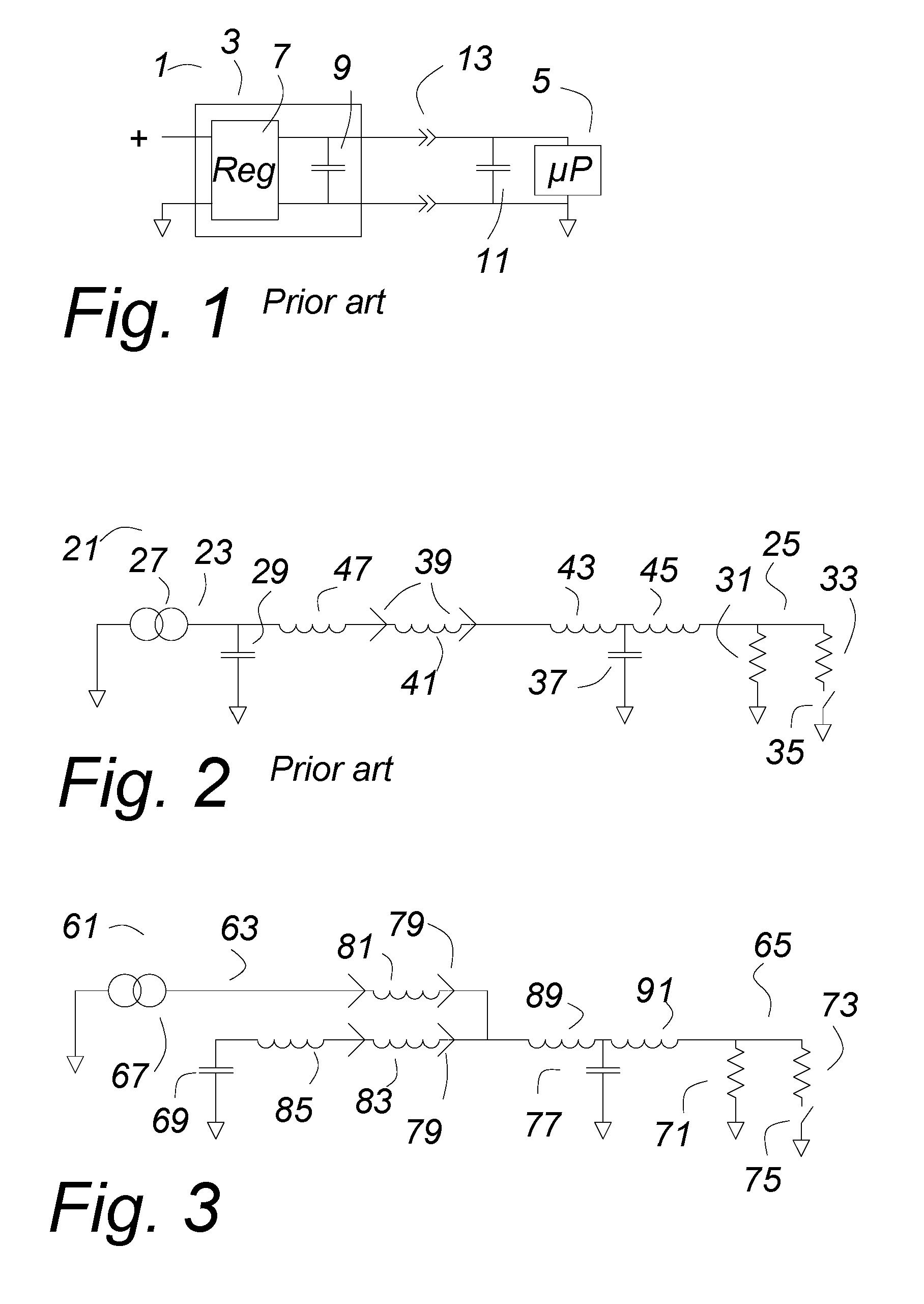
[0033]FIG. 1 shows a power supply system 1 comprising a power supply 3 connected through a connector 13 to an output load 5 shown as a microprocessor. There will likely be one or more decoupling capacitors 11 near the load. The power supply 3 comprises a power converter 7 shown as a voltage regulator as an illustration, not a limitation, and an output capacitor 9. The voltage regulator 7 may be a buck regulator, as an example.

[0034]In this specification and the claims, a “power supply” is an assembly for providing power to a load. It is usually, but not necessarily, connected to the load through two or more contacts of a connector so that the power supply is a separate assembly and can be separated from the load by unplugging the connector. A power supply usually comprises a “power converter” and an “output capacitor”. In this specification and the claims, a “power converter” is a source of current, and may be either a voltage regulator or a controlled current source. Recitation of ...


PUM


Abstract

In a low voltage, high current power supply having very fast transitions of the load current, as in certain power supplies for microprocessors, the circuit impedances, particularly the stray inductance of the connector, are a major problem. If the voltage regulator circuits are separated from the output capacitor and brought to separate contacts in the connector, only connecting together on the load side, the voltage regulator will be much better able to overcome the connector impedance. The connector may be a printed connector, in which the metal surfaces of the internal layers of a multilayer printed circuit card are extended successively and mate with a similar complementary printed connector. To overcome high frequency effects, the power bus is a multilayer interleaved bus. Vias conduct the high frequency component of the current much more effectively at the edge of a stack of foil layers, so the power bus is strongly digitated to increase the periphery.

Description

CROSS REFERENCE TO RELATED APPLICATIONS[0001]This application is a continuation in part application of a provisional patent application Ser. No. 60 / 521,031 entitled “Connector with Current Injection”, filed 7 Feb., 2004.[0002]This application is also a continuation in part application of a provisional patent application Ser. No. 60 / 522,952, entitled “Connection System for Fast Power Converters”, filed 24 Nov., 2004.[0003]Priority to those dates is claimed.BACKGROUND OF THE INVENTION[0004]In a fast power supply that must provide low voltage, high current power with very fast current transitions and tight regulation, the inductance of the connection system is a serious problem. To drive fast transitions of current through the inductance of the connector requires a significant voltage across the connector, but that is incompatible with holding tight voltage regulation.[0005]Often a fairly large capacitor is used on the output of the power supply. One function of this capacitor is to re...

Claims


Application Information

Patent Timeline
Patent Type & Authority Patents(United States)
IPC IPC(8): H01R12/00
CPCH02M7/003H05K1/0265H05K1/117H05K1/0298H05K2201/09845H05K3/36H05K2201/0919H05K2201/09618H05K2201/09672H05K1/142H05K1/0231H05K1/162H05K2201/097
Inventor HERBERT, EDWARD
Owner HERBERT EDWARD
Why Eureka
Try Eureka