
Filtration method and installation

a technology of liquid separation and installation method, which is applied in the direction of filtration separation, moving filter element filter, separation process, etc., can solve the problems of catalyst attrition, catalyst attrition, and filtration rate may drop below acceptable levels, and research has focused on attrition resistant ltft catalysts, but without much success

Inactive Publication Date: 2009-10-22
EQUINOR ENERGY AS +1
View PDF8 Cites 10 Cited by
  • Summary
  • Abstract
  • Description
  • Claims
  • Application Information

AI Technical Summary

Benefits of technology

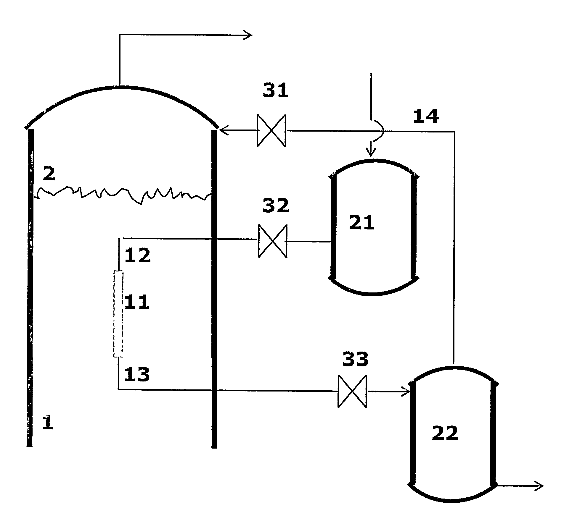
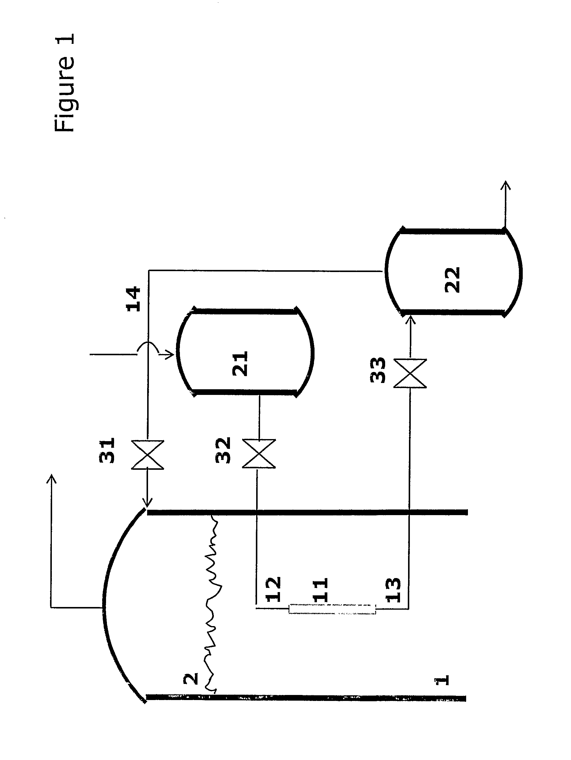
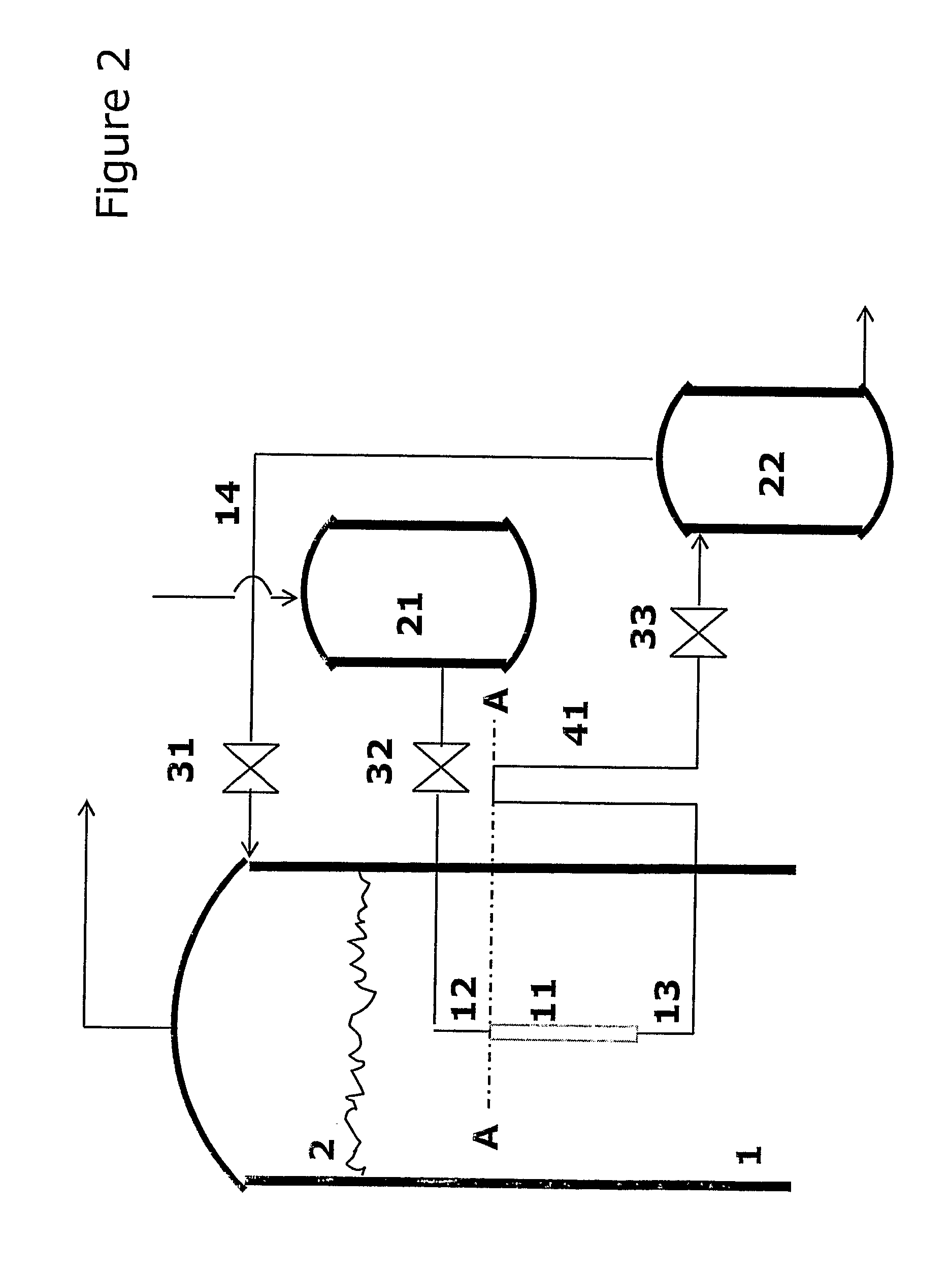
[0008]c) applying a backwashing pressure differential opposite to the filtering pressure differential to force a backflushing fluid in an opposite direction across the filter media to dislodge filter cake build-up.
[0016]The charging pressure of the rinsing fluid when charging the inside of the filter element should be lower or similar to the pressure at the outside of the filter element; in the slurry phase, to minimize transport of the said rinsing fluid across the filter element into the slurry phase.

Problems solved by technology

However, catalyst fines may be trapped in the filter openings or collected on the filtrate side of the filter, and eventually, despite backflushing, the filtration rate may decrease below acceptable levels.
However, catalyst attrition occurs in a slurry bubble column reactor, and over time catalyst fines outside the selected range are formed inside the column.
As a result a lot of research has focused on attrition resistant LTFT catalysts, without much success due to high flow velocities inside a slurry bubble column reactor.
However, catalyst fines inside the filter pores and on the filtrate side of the filter remain trapped.

Method used


Image

  • Filtration method and installation
  • Filtration method and installation
  • Filtration method and installation

Examples


example 1

[0092]In this first example a LTFT three phase slurry reactor with 2.7 m inner diameter and a height of 28 m, and with a filtration method according to the present invention installed in an embodiment as illustrated in FIG. 5 was used.

[0093]The installation included a plurality of hollow filter elements closed in both ends, immersed in a vertical orientation in the slurry. The filter elements were located in filter element groups. The filter media of the filter elements was manufactured from stainless steel woven wire mesh having an average pore size of 70 μm. The concentration of catalyst particles in the slurry in this experiment was 8 weight %, with a particle size distribution as given below:

[0094]<100 μm 95 vol %

[0095]<70 μm 50 vol %

[0096]<25 μm 10 vol %

[0097]<5 μm 3 vol %

[0098]The pressure of the LTFT slurry reactor was 1600 kPag.

[0099]During the filtration step a filtering pressure differential of 0.01-100 kPa across the filter elements and the filter cakes built up on the ou...

example 2

[0102]In this example a LTFT three phase slurry reactor, with 55 mm inner diameter and a height of 5 m and with a filtration method according to the present invention installed in an embodiment as illustrated in FIG. 9 was used. The installation included one single hollow filter element closed in both ends, immersed in a vertical orientation in the slurry. The filter media of the filter element was manufactured from stainless steel woven wire mesh having an average pore size of 70 μm. The concentration of catalyst particles in the slurry in this experiment was 12 weight %, with a particle size distribution as given below:

[0103]<100 μm 95 vol %

[0104]<70 μm 50 vol %

[0105]<25 μm 10 vol %

[0106]<5 μm 3 vol %

[0107]The pressure of the LTFT slurry reactor was 2000 kPag.

[0108]During the filtration step a filtering pressure differential of 0.01-30 kPa across the filter element and the filter cake built up on the outside of the filter element was applied to obtain and withdraw a filtrate from ...


PUM

PropertyMeasurementUnit
Temperatureaaaaaaaaaa
Pressureaaaaaaaaaa
Flow rateaaaaaaaaaa

Abstract

The invention provides a method for the separation of liquid from a three phase slurry bubble column. The method includes the step of charging the inside of a hollow filter element with a rinsing fluid to clean the inside of the filter for catalyst fines followed by a backflushing step. The invention also provides an installation for the separation of liquid from a three phase slurry bubble column. The installation includes at least one hollow and enclosed filter element and one or more conduits in fluid communication with the internal volume of filter, with at least one conduit being configured or connected for inflow of rinsing fluid and at least one conduit being configured or connected for outflow of rinsing fluid.

Description

TECHNICAL FIELD OF THE INVENTION[0001]This invention relates to a method and installation for the separation of liquid from a slurry bubble column reactor.BACKGROUND TO THE INVENTION[0002]Slurry bubble column reactors are well known in the art and widely used as reactors for Low Temperature Fisher-Tropsch (LTFT) processes. LTFT processes include the step of bubbling synthesis gas, consisting mainly of carbon monoxide and hydrogen, through a column of hydrocarbon liquid wherein catalyst particles are suspended. The synthesis gas reacts in the presence of the catalyst to form predominantly liquid hydrocarbons. The liquid hydrocarbons are separated from the column, normally by filtration. The filters are preferably inside the column. The catalyst particle size distribution and filter mesh size is normally within a selected range. Typically such filters are manufactured from stainless steel woven wire mesh, sintered metal, wedge wire or ceramic filter elements. Often filter cake builds ...

Claims


Application Information

Patent Timeline
IPC IPC(8): B01D29/62
CPCB01J8/006C10G2/342B01J8/228B01J8/22
Inventor MINNIE, OCKERT RUDOLPHTAYLOR, PATRICK OTTOSORAKER, PALFATHI, MARCUS
Owner EQUINOR ENERGY AS
Learn More